Two-section type lifting deceleration strip

A deceleration belt, two-stage technology, applied in the field of two-stage lifting deceleration belt, can solve the problem of low function of deceleration belt, achieve fast response, good lifting function, stable and simple control

Inactive Publication Date: 2021-04-09
王雷
View PDF9 Cites 0 Cited by
  • Summary
  • Abstract
  • Description
  • Claims
  • Application Information

AI Technical Summary

Problems solved by technology

[0004] The purpose of the present invention is to solve the problem of low function of speed bumps in the prior art, and propose a two-stage lifting speed bump

Method used


Image

  • Two-section type lifting deceleration strip
  • Two-section type lifting deceleration strip

Examples


Embodiment

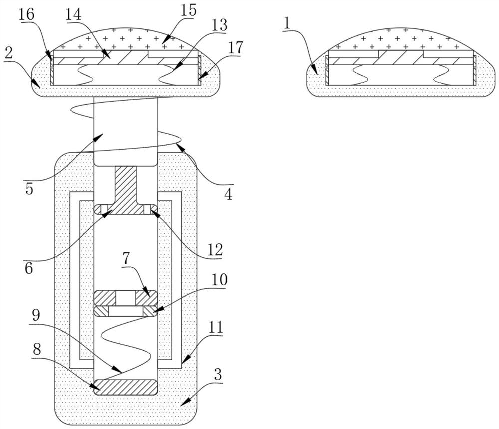
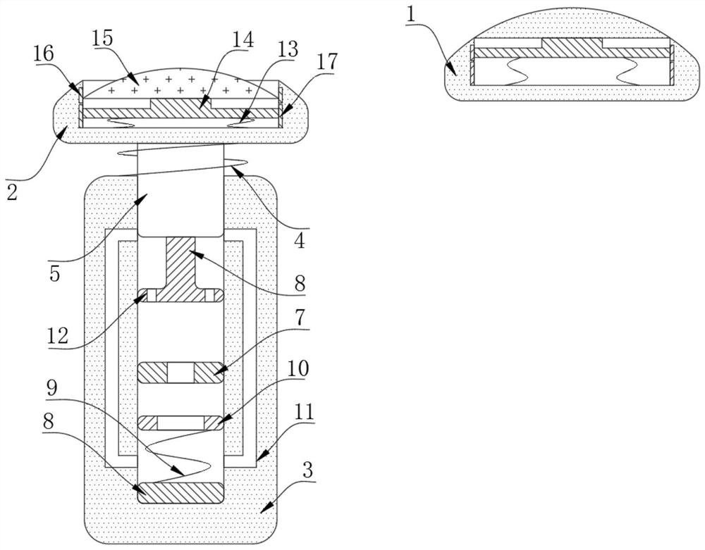
[0021] refer to Figure 1-2 , a two-stage lifting deceleration belt, including a front end 1, a rear end 2 and a buried column 3, the interior of the front end 1 and the rear end 2 are equipped with a starting mechanism, and the upper end of the buried column 3 is connected to the rear end 2 through a return spring 4 , the bottom of the rear end 2 is fixed with a sliding rod 5 that is sealingly and slidingly connected with the inner wall of the buried column 3, and the bottom of the sliding rod 5 is fixed with a push plate 6 that is sealingly and slidingly connected with the inner wall of the buried column 3, and the inner wall of the buried column 3 is fixed with a spacer ring 7. The bottom of the buried column 3 is provided with a pushback mechanism.

[0022] The push-back mechanism includes a suction block 8 fixed on the bottom of the buried column 3, the suction block 8 is an electromagnet, the upper end of the suction block 8 is connected with a push-back ring 10 through ...


PUM


Abstract

The invention discloses a two-section type lifting deceleration strip which comprises a front end, a rear end and an embedded column, starting mechanisms are arranged in the front end and the rear end correspondingly, the upper end of the embedded column is connected with the rear end through a reset spring, and a sliding rod connected with the inner wall of the embedded column in a sealed and sliding mode is fixed to the bottom of the rear end; a push plate connected with the inner wall of the embedded column in a sealed and sliding mode is fixed to the bottom of the sliding rod, a spacer ring is fixed to the inner wall of the embedded column, and a push-back mechanism is arranged at the bottom of the embedded column. The two-section type lifting deceleration strip has the advantages that the electrorheological fluid is arranged and can be solidified and expanded after being electrified to support the sliding rod, then the rear end can be effectively manufactured, height adjustment can be easily controlled by controlling the loss amount of the electrorheological fluid, overall control is relatively stable and simple, mechanical damage is not likely to happen, the service life is relatively long, the response speed is very high, and a good lifting function can be achieved.

Description

technical field [0001] The invention relates to the technical field of road facilities, in particular to a two-stage lifting deceleration belt. Background technique [0002] Traffic speed bumps, also called speed bumps, are traffic facilities installed on highways to slow down passing vehicles. Generally, yellow and black are alternated to attract visual attention, and the road surface is slightly arched to achieve the purpose of vehicle deceleration. It is generally set at highway crossings, industrial and mining enterprises, schools, residential quarters, etc., where vehicles need to slow down and where traffic accidents are likely to occur. It is a new type of special traffic safety setting for reducing the speed of motor vehicles and non-motor vehicles; [0003] The existence of the deceleration belt will inevitably cause the vehicle to bump, and then achieve the deceleration effect. However, the height of the existing deceleration belt cannot be changed, and vehicles o...

Claims


Application Information

Patent Timeline
Patent Type & Authority Applications(China)
IPC IPC(8): E01F9/529E01F13/10F16F9/53
CPCE01F9/529E01F13/105F16F9/532
Inventor 王雷
Owner 王雷
Why Eureka
Try Eureka