Universal shooting frame for long guns and short guns

A short gun and rear clamping technology, which is applied in weapon accessories, offensive equipment, weapon testing, etc., can solve the problems of potential safety hazards, unreliable clamping force firing, damage to guns, etc., and achieve the effect of avoiding unreliable firing

Active Publication Date: 2017-07-07
卡目索纳智能科技研发(江苏)有限公司
View PDF6 Cites 8 Cited by
  • Summary
  • Abstract
  • Description
  • Claims
  • Application Information

AI Technical Summary

Problems solved by technology

[0004] In order to overcome the problems in the background technology, the present invention proposes a general-purpose shooting frame for long and short guns. If the clamping force is too small, there will be safety hazards in the unstable shooting. The present invention can effectively clamp the detected gun reliably, clamp The holding force can be adjusted, and the size of the holding force can be displayed, thus avoiding the problem of unreliable firing and even damage to the gun due to excessive holding force caused by blind adjustment

Method used


Image

  • Universal shooting frame for long guns and short guns
  • Universal shooting frame for long guns and short guns
  • Universal shooting frame for long guns and short guns

Examples


Embodiment 1

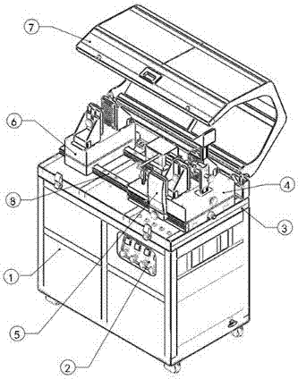
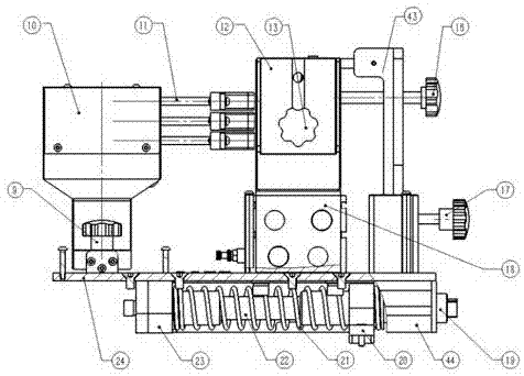
[0038] When clamping the short gun, first move the front support frame 10 to the front end of the slideway 25 and lock it by the locking screw I9. Then install the short gun movable pin shaft in the pin shaft hole sleeve 26 on the rear clamping block 14, adjust the short gun muzzle adjustment part 15 to a suitable height, lock it through the stop screw III17, start the air compressor 49, adjust the rear clamp Hold the pressure knob 35 to start the corresponding power actuator 39 so that the compressed gas enters the cylinder of the two synchronous jaws I18, pushes the rear clamping block 14 on the two synchronous jaws I18 to clamp the rear seat of the short gun, and passes The finger pressure knob 53 starts the power executive element 39 to promote the finger 11 on the support frame 10 to clamp the front end of the short gun. After the short gun is clamped, the adjusting screw 16 is adjusted to realize the adjustment of the muzzle position of the short gun.

[0039] Then, the ...

Embodiment 2

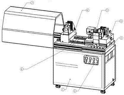
[0041] When clamping a long gun, move the front support frame 10 and the finger 11 installed on it to the rear end of the slideway 25 and lock it with the set screw I9, remove the pin hole sleeve 26 and the muzzle adjustment of the short gun Part 15, change the long gun rear seat 27, the long gun rear seat is placed on the long gun rear seat 27, the long gun muzzle is placed on the support member 30, then, start the air compressor 49, adjust the clamping pressure knob 35 to start and The corresponding power actuator 39 makes the compressed gas enter the cylinder of the two synchronous jaws I18, pushes the rear clamping block 14 on the two synchronous jaws I18 to clamp the rear seat of the long gun, and at the same time, opens the front clamping pressure Knob 52 starts its corresponding power execution element 39 to promote two synchronous jaws II 32 to clamp the muzzle of the long gun.

[0042] Then, the magnetic suction base 55 is sucked on the base 1, the net bag 57 is adjus...


PUM


Abstract

The invention relates to a universal shooting frame for long guns and short guns, and belongs to the technical field of detection and identification of firearms. The universal shooting frame for long guns and short guns comprises a base, a muzzle height adjusting platform, a rear clamping unit, a percussion unit, a front clamping unit and a linear sliding guide track, wherein the muzzle height adjusting platform is arranged on the top of the base; the linear sliding guide track is arranged on the muzzle height adjusting platform; the rear clamping unit is arranged on the linear sliding guide track; and the percussion unit is arranged on the rear clamping unit. By the universal shooting frame for long guns and short guns, a detected gun can be reliably clamped effectively, the magnitude of a clamping force is adjustable and is accurately displayed on a display original part, and therefore, the problems that percussion is unreliable and even a gun is damaged due to over-large clamping force caused by blind adjustment, the gun cannot be clamped stably due to too small clamping force, and potential safety hazards exist are avoided.

Description

technical field [0001] The invention belongs to the technical field of firearm detection and identification, and in particular relates to a universal shooting rack for long and short guns. Background technique [0002] In the detection and litigation stages of gun-related cases, the identification of firearms provides the most basic evidence for the direction of investigation and detection, narrowing the scope of investigation, identifying the firing of guns, and exposing and proving crimes. This equipment is one of the important equipment for gun inspection and identification, and it forms a bullet inspection and identification system with bullet speedometer, bullet collector and bullet mark contrast instrument. Therefore, the operation convenience, stability and safety of gun clamping are of great significance in gun inspection and identification. [0003] Domestic existing dangerous firearm shooting frame has following deficiency: 1, adopt pure mechanical structure mostl...

Claims


Application Information

Patent Timeline
Patent Type & Authority Applications(China)
IPC IPC(8): F41A31/00
CPCF41A31/00
Inventor 刘益潘楠薛玉春杨松
Owner 卡目索纳智能科技研发(江苏)有限公司
Why Eureka
Try Eureka