Riveting joint geometric parameter detection method

A detection method and a technology of geometric parameters, which are applied in the field of detection of geometric parameters of riveted joints, can solve the problems of being unsuitable for industrial production, labor-intensive, and time-consuming, and achieve the effects of reducing measurement errors, improving measurement efficiency, and accurate detection

Active Publication Date: 2017-07-07
WUHAN UNIV OF TECH
View PDF5 Cites 8 Cited by
  • Summary
  • Abstract
  • Description
  • Claims
  • Application Information

AI Technical Summary

Problems solved by technology

This method is time-consuming, laborious and not suitable for industrial production

Method used


Image

  • Riveting joint geometric parameter detection method
  • Riveting joint geometric parameter detection method
  • Riveting joint geometric parameter detection method

Examples


Embodiment ( 1

[0052] Step 1: Establish a steel and aluminum riveting analysis model in the finite element software, where the upper sheet is a 1.6mm thick steel plate DP590, and the lower sheet is a 1.5mm thick aluminum alloy AA6061-T6;

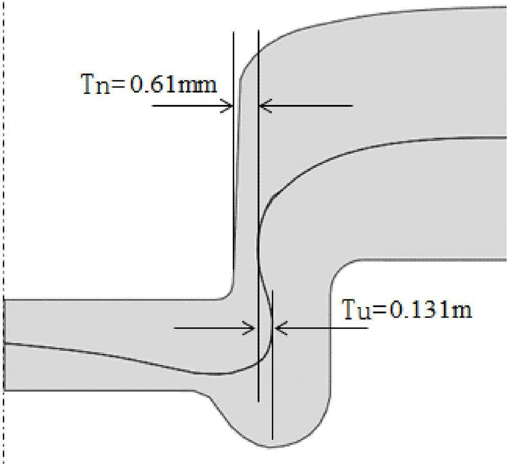
[0053] Step 2: Measure the neck thickness and interlock value of the model calculated by the finite element software, such as image 3 Shown, the neck thickness T n 0.61mm, interlock value T u is 0.131mm, the constant C is obtained by the following formula, where,

[0054] C=T n +T u =0.61+0.131=0.741mm

[0055] Choose L 25 (5 6 ) Orthogonal test table, in the finite element software, the impact of the punch diameter, punch draft angle, punch fillet, die groove depth and die depth on the neck thickness value and interlock value of the die is studied. The test table and simulation results are shown in Table 1, and the neck thickness value and interlock value of each group are analyzed, so that

[0056]

[0057] Among them, L 1 is the punch diame...

Embodiment ( 2

[0065] Step 1: Carry out self-piercing riveting tests on steel and aluminum without rivets. The upper sheet is 1.6mm thick steel plate DP590, and the lower sheet is 1.5mm thick aluminum alloy AA6061-T6. Two riveted joints under different process parameters Make a number.

[0066] Step 2: Cut 1# riveted joint, such as Figure 6 As shown, use the measuring tool to measure the neck thickness value and interlock value of the connection section, the neck thickness value T n 0.58mm, interlock value T u is 0.17mm, so the constant C is:

[0067] C=T n +T u =0.58+0.17=0.75mm

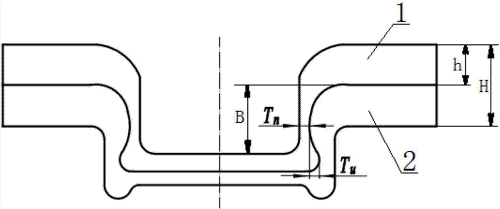
[0068] Step 3: Use an ultrasonic thickness gauge to measure the thickness of the upper sheet within the range of B several times along the inner side of the 2# riveted joint, and then select the minimum value from the multiple measurement results as the neck thickness of the riveted joint, namely:

[0069] T n =min(0.63, 0.61, 0.85, 0.56, 0.57, 0.73, 0.89) mm

[0070] Measurement result T n is 0.56mm.

...


PUM


Abstract

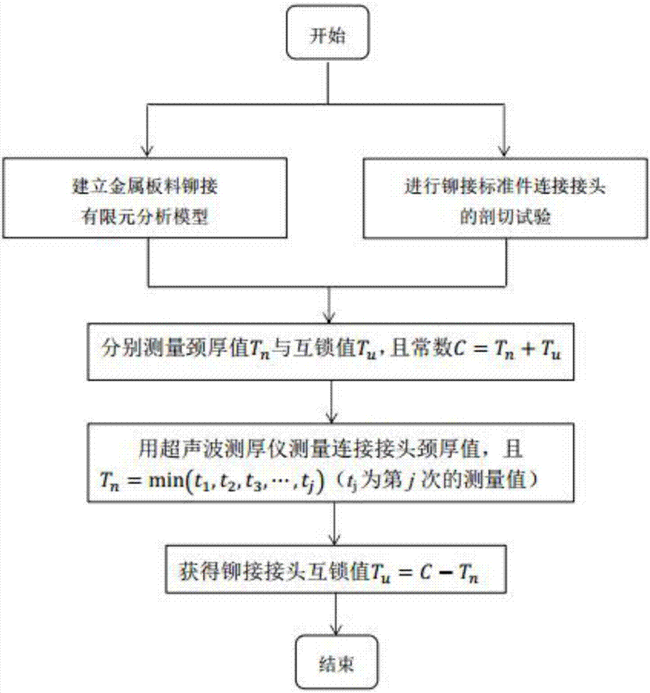
The invention relates to a riveting joint geometric parameter detection method. The method comprises the following steps that: a riveting analysis model is built in finite element analysis software, and a plurality of groups of mechanical clinching connection processes are simulated through the analysis model, the corresponding riveting constants C of two kinds of corresponding riveting material plates of a riveting joint are obtained, and it is proved that that the riveting constant C can be expressed through an equality that C=Tn+Tu, wherein Tn is a neck thickness value, and Tu is an interlocking value; a thickness measuring instrument is utilized to determine a measurement area B along the inner side of the riveting joint; the thickness measuring instrument is utilized to measure the neck thickness value Tn of the riveting joint in the measurement area B along the inner side of the riveting joint; and the interlocking value Tu which can be expressed through the equality Tu=C-Tn is obtained through the riveting constant C and the neck thickness value. With the riveting joint geometric parameter detection method adopted, fast and accurate detection of the geometrical parameters of the mechanical clinching riveting joint can be realized, nondestructive measurement can be realized, the measurement efficiency of the riveting joint is improved, and measurement errors are reduced.

Description

technical field [0001] The invention relates to the technical field of material connection, in particular to a method for detecting geometric parameters of riveted joints. Background technique [0002] Lightweight has become an inevitable trend in the development of industries such as automobiles, aviation, and aerospace, and the extensive use of advanced lightweight materials such as aluminum alloys and high-strength steels is an important means to achieve lightweight at this stage. Due to the huge difference in thermal physical properties of steel and aluminum and the formation of brittle intermetallic compounds in the weld, it is difficult to achieve dissimilar connections between steel and aluminum by conventional resistance spot welding. [0003] Rivetless self-piercing riveting is an emerging connection technology, which can overcome the technical bottleneck of the resistance spot welding process in connecting dissimilar metals. The material has the advantages of no d...

Claims


Application Information

Patent Timeline
Patent Type & Authority Applications(China)
IPC IPC(8): G01B21/00G01B17/02G01B11/06
CPCG01B11/06G01B17/02G01B21/00
Inventor 宋燕利华林朱根鹏徐勤超
Owner WUHAN UNIV OF TECH
Why Eureka
Try Eureka