
Test device for large deformation shearing seepage of contact surface and use method thereof

A test device and contact surface technology, applied in the direction of applying stable shear force to test material strength, measurement device, test wear resistance, etc., can solve the problem of limiting shear dislocation deformation, sealing film and soil samples are prone to occur Extrusion, test cannot be carried out and other problems, to achieve the effect of ensuring accuracy, reasonable loading method, and avoiding extrusion

Pending Publication Date: 2017-07-07
TSINGHUA UNIV
View PDF9 Cites 7 Cited by
  • Summary
  • Abstract
  • Description
  • Claims
  • Application Information

AI Technical Summary

Problems solved by technology

At present, there is a traditional contact surface shear test device, but it can only unilaterally measure the stress-deformation characteristics of the contact surface between the soil and the structure
In addition, there is "a test device for measuring the seepage and erosion characteristics of the contact surface between soil and structure". The test cannot be performed; and its contact panel relies on spring support, which limits the maximum shear misalignment deformation that can be generated

Method used


Image

  • Test device for large deformation shearing seepage of contact surface and use method thereof
  • Test device for large deformation shearing seepage of contact surface and use method thereof
  • Test device for large deformation shearing seepage of contact surface and use method thereof

Examples


Embodiment Construction

[0022] The present invention will be described in detail below in conjunction with the accompanying drawings and embodiments.

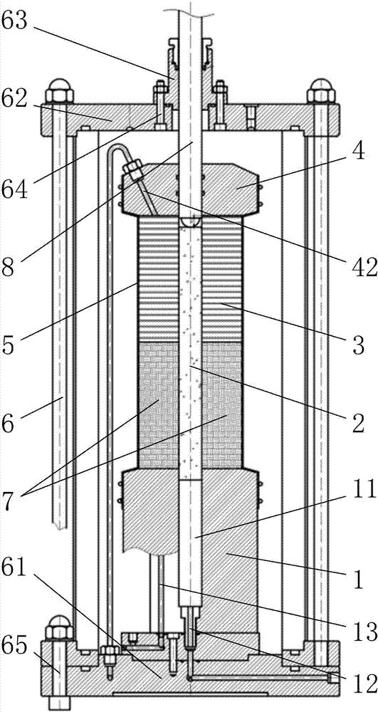
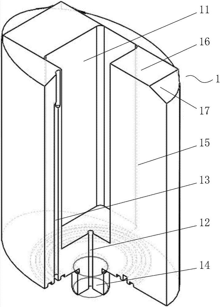
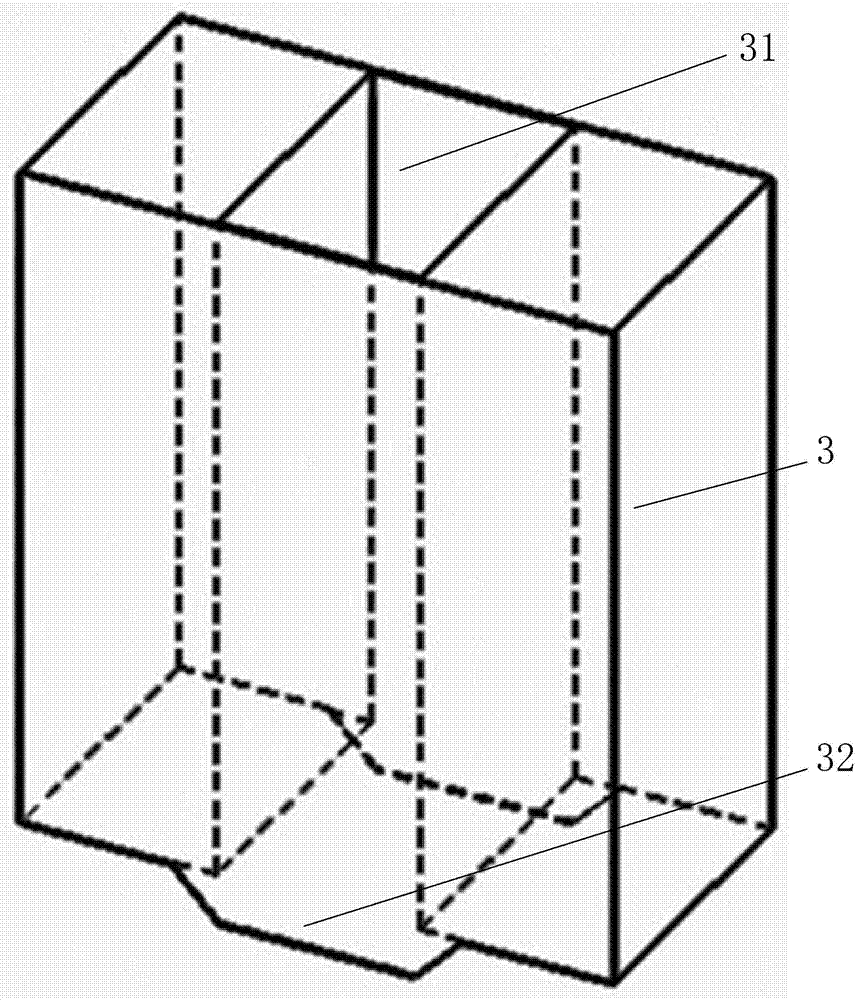
[0023] Such as Figure 1 to Figure 4 As shown, the present invention provides a contact surface large deformation shear seepage test device, which includes a base 1 , a contact panel 2 , a sleeve 3 , a top cap 4 and a sealing film 5 . Among them, the base 1 is used to be fixedly installed on the pressure chamber base 61 of the pressure chamber 6 of the triaxial shearing instrument. The top of the base 1 is provided with a deep groove 11, and the bottom of the deep groove 11 is provided with a direction parallel to the shear plane. The seepage outlet pipeline 12 is also provided inside the base 1 with a seepage outlet pipeline 13 in a direction perpendicular to the shear plane. The contact panel 2 can be installed in the deep groove 11 through the lower part, and the two sides of the middle part of the contact panel 2 are used for close contact with t...


PUM


Abstract

The invention relates to a test device for large deformation shearing seepage of a contact surface and a use method thereof. The test device comprises a base, a contact panel, a sleeve, a top cap and sealing films, wherein a deep slot is formed at the top of the base; two side faces of the middle part of the contact panel are in tight contact with soil samples; a mounting hole is formed at the center of the sleeve; the top cap is supported at the top of the sleeve; the sealing films are used for wrapping the peripheries of the base, the soil samples on the two sides of the contact panel, the sleeve and the top cap; a seepage water draining pipeline parallel to a shearing surface direction and a seepage water draining pipeline vertical to the shearing surface direction are arranged in the base; the contact panel is arranged in the deep slot through the lower part; the cross sectional dimension of the contact panel is smaller than the cross sectional dimension of the deep slot; the sleeve is sleeved on the part of the upper part of the contact panel, higher than the soil samples, through the mounting hole; the cross sectional dimension of the mounting hole is greater than the cross sectional dimension of the contact panel; a piston rod hole is formed at the center of the top cap; a piston rod penetrates through the top cap and directly acts on the contact panel; a seepage water feeding pipeline parallel to the shearing surface direction and a seepage water feeding pipeline vertical to the shearing surface direction are arranged on the top cap.

Description

technical field [0001] The invention relates to a mechanical and seepage characteristic test device of a contact surface in geotechnical engineering and a method of use thereof, in particular to a large deformation shear seepage test device of a contact surface and a method of use thereof. Background technique [0002] Under the action of external load, large shear dislocation deformation often occurs at the interface between soil and structure. At this time, under the action of complex stress and seepage, the soil is prone to shear and seepage damage, which poses a threat to the safety of geotechnical structures. Therefore, the research on the shear penetration failure characteristics of the contact surface between soil and structure when large shear dislocation occurs has important engineering practical value. [0003] It is a basic method to study the above-mentioned problems by conducting seepage tests on the contact surface between soil and structure under the conditio...

Claims


Application Information

Patent Timeline
IPC IPC(8): G01N3/24G01N3/56
CPCG01N3/24G01N3/567G01N2203/0025
Inventor 刘千惠吴永康吕禾于玉贞张丙印
Owner TSINGHUA UNIV
Learn More