
Plate detection device

A detection device and plate technology, which is applied in the direction of instruments, counting objects, and counting of stacked items, etc., can solve the problems of wasting plates, low detection success rate, inability to accurately distinguish whether one or multiple overlapping sheets, etc., and achieve rapid detection operation. , the effect of simple operation

Pending Publication Date: 2017-07-07
SHANGHAI FANUC ROBOTICS
View PDF13 Cites 1 Cited by
  • Summary
  • Abstract
  • Description
  • Claims
  • Application Information

AI Technical Summary

Problems solved by technology

[0002] Before the automobile sheet is processed by the mold on the production line, the raw material sheet will be sent to the mold for processing, but it is not possible to accurately distinguish whether it is one sheet or multiple overlapping sheets each time. Processing will not only cause damage to the mold, but also cause defective products to appear, and the waste of plates will lead to an increase in production costs. Therefore, it is necessary to detect the number of plates before transferring the plates. The existing multiple detection methods include single Head-type detection, double-head non-contact detection using the principle of electromagnetic induction and double-layer non-contact detection based on triangulation. The above-mentioned detection methods have the following defects. The single-head contact type requires a controller program for different thicknesses of plates. The adjustment cannot be used universally. The contact detection method requires the plate and the detection probe to fit together, so the detection success rate is low. The through-beam detection method requires a certain detection area, which is not conducive to the installation of the gripper for grabbing the plate.

Method used


Image

  • Plate detection device
  • Plate detection device

Examples


Embodiment Construction

[0034] The following will clearly and completely describe the technical solutions in the embodiments of the present invention with reference to the accompanying drawings in the embodiments of the present invention. Obviously, the described embodiments are only some, not all, embodiments of the present invention. Based on the embodiments of the present invention, all other embodiments obtained by persons of ordinary skill in the art without creative efforts fall within the protection scope of the present invention.

[0035] It should be noted that, in the case of no conflict, the embodiments of the present invention and the features in the embodiments can be combined with each other.

[0036] The present invention will be further described below in conjunction with the accompanying drawings and specific embodiments, but not as a limitation of the present invention.

[0037] The technical solution of the present invention includes a plate detection device.

[0038] Such as Fi...


PUM


Abstract

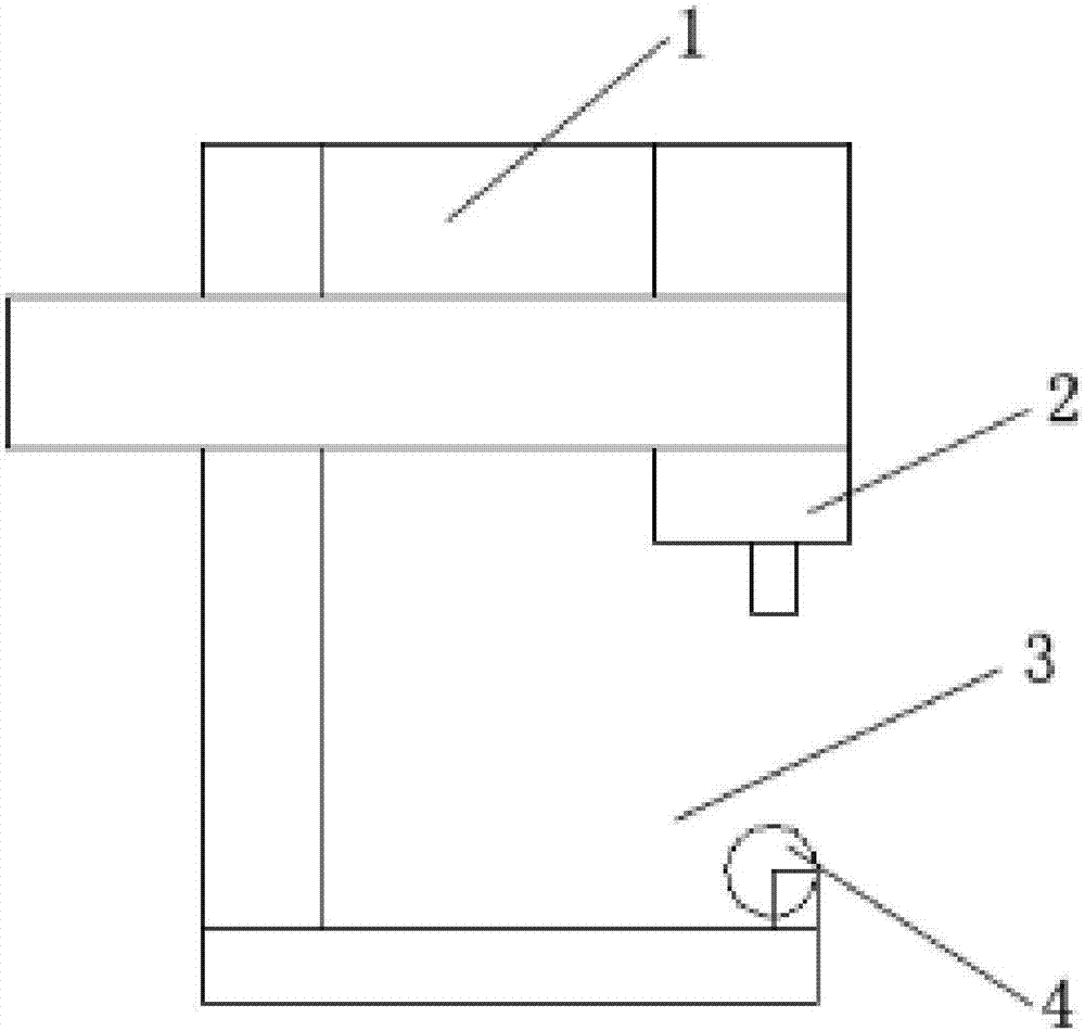
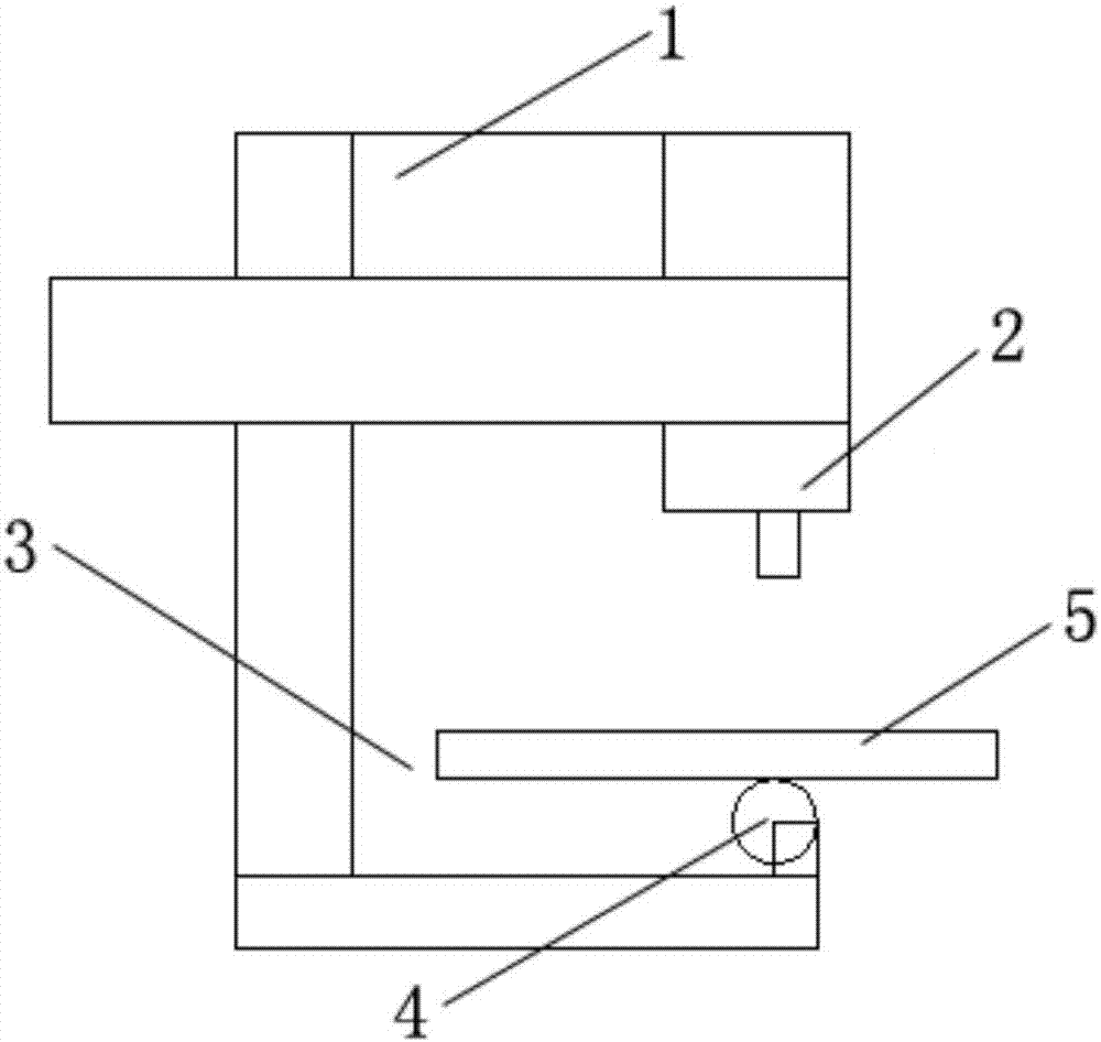
The present invention provides a plate detection device. The plate detection device is used for detecting the number of plates. The plate detection device comprises a servo motor, a movable mechanism, a servo driver, an arrangement area and a triggering unit; the servo driver is used for controlling the servo motor to work, so that the servo motor drives the movable mechanism to move towards a direction where plates are placed or a direction opposite to the direction where the plates are placed; the arrangement area is used for bearing the detected plates; the triggering unit is used for forming a triggering signal when the plates contact with the triggering unit and sending the triggering signal to the servo driver; the servo driver controls the servo motor to work according to the triggering signal so that the servo motor can drive the movable mechanism to contact with the plates; the servo driver forms feedback current according to the movement stroke of the movable mechanism driven by the servo motor and judging whether the feedback current is larger than a preset current value; if the feedback current is larger than the preset current value, the number of current detected plates is larger than 1; if the feedback current is not larger than the preset current value, one plate which is currently detected exists. With the plate detection device adopted, the defect of poor applicability caused by a condition that control programs in a controller should be modified according to plates with different thickness in the prior art can be eliminated.

Description

technical field [0001] The invention relates to the field of auto parts detection, in particular to a plate detection device. Background technique [0002] Before the automobile sheet is processed by the mold on the production line, the raw material sheet will be sent to the mold for processing, but it is not possible to accurately distinguish whether it is one sheet or multiple overlapping sheets each time. Processing will not only cause damage to the mold, but also cause defective products to appear, and the waste of plates will lead to an increase in production costs. Therefore, it is necessary to detect the number of plates before transferring the plates. The existing multiple detection methods include single Head-type detection, double-head non-contact detection using the principle of electromagnetic induction and double-layer non-contact detection based on triangulation. The above-mentioned detection methods have the following defects. The single-head contact type requ...

Claims


Application Information

Patent Timeline
Patent Type & Authority Applications(China)
IPC IPC(8): G06M9/00
CPCG06M9/00
Inventor 朱益晨贾文杰杜江波赵至伟
Owner SHANGHAI FANUC ROBOTICS
Learn More