
A gear groove width detection device

A detection device, gear groove technology, applied in the direction of measuring devices, instruments, etc., can solve the problems of difficult detection operation, poor precision, large reading error, etc., to achieve the effect of meeting the detection efficiency, simple detection operation and meeting the construction needs

Active Publication Date: 2022-03-18
东风汽车零部件集团有限公司刃量具分公司
View PDF5 Cites 0 Cited by
  • Summary
  • Abstract
  • Description
  • Claims
  • Application Information

AI Technical Summary

Problems solved by technology

[0005] 1) By observing which of the three steps can pass, the range of the groove width can be judged, but the actual size of the groove width cannot be measured
[0006] 2) It may be necessary to use a variety of slot clamps and measure multiple times before finally judging the actual range of the slot width
[0009] 1) There are many detection operations, and the detection size may not be judged by one operation. It needs repeated detection to determine the size range (Scheme 1)
Or during detection, the detection operation is difficult (Scheme 2)
[0010] 2) The detection can only judge the range of the measured size (Scheme 1), or the detection is unstable, the reading error is large, and the accuracy is poor (Scheme 2)
[0011] 3) The test results cannot be automatically displayed, and it is not convenient for the control system to automatically record the test results, which cannot meet the construction needs of digital factories (Schemes 1 and 2)

Method used


Image

  • A gear groove width detection device
  • A gear groove width detection device
  • A gear groove width detection device

Examples


Embodiment Construction

[0038] pass below Figure 1 ~ Figure 2 As well as listing some optional embodiments of the present invention, the technical solutions (including preferred technical solutions) of the present invention are further described in detail. Apparently, the described embodiments are only some of the embodiments of the present invention, not all of them. Based on the embodiments of the present invention, all other embodiments obtained by persons of ordinary skill in the art without creative efforts fall within the protection scope of the present invention.

[0039] like figure 2 , Figure 6 and 7 As shown, the gear groove width detecting device designed by the present invention includes:

[0040] The main body 3 for positioning the upper step surface of the gear 1, the positioning sleeve 4 located in the main body 3 for positioning the gear shaft 2, the measuring mechanism located on both sides of the main body for measuring the groove width and the device for driving the measurin...


PUM


Abstract

The invention discloses a gear groove width detection device, which comprises: a body for positioning the upper step surface of the gear, a positioning sleeve located in the body for positioning the gear shaft, a measuring mechanism located on both sides of the body for measuring the groove width, and The transmission mechanism that drives the measurement structure to move along the groove width; the measurement mechanism includes: measuring rods symmetrically arranged on both sides of the body; The strut spring between them and the connecting plate passing through the sliding strut; the two ends of the connecting plate are respectively hinged with the measuring rod. The detection operation of the invention should be simple and fast, and the detection can be completed with only one operation; at the same time, the error is small and the precision is high; and the detection results can be displayed digitally, which is convenient for the control system to automatically record the detection results and meet the construction needs of digital factories.

Description

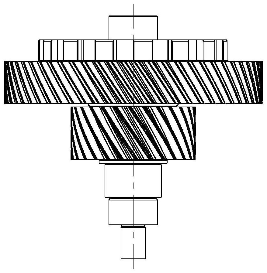
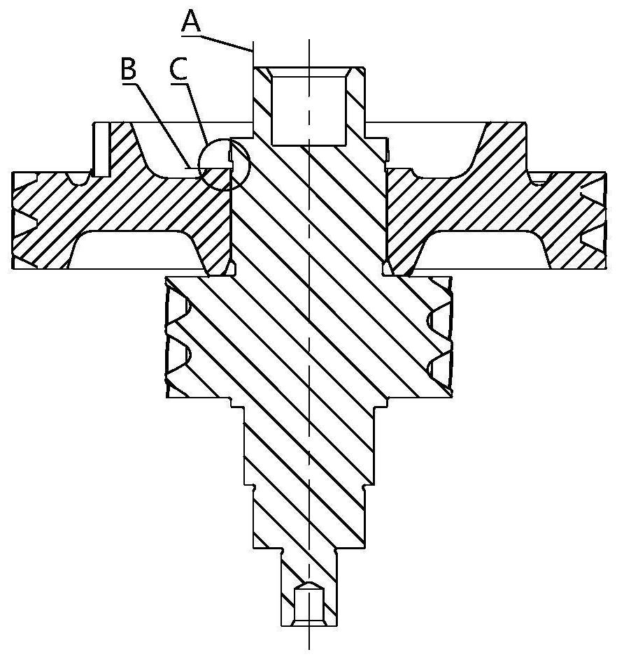
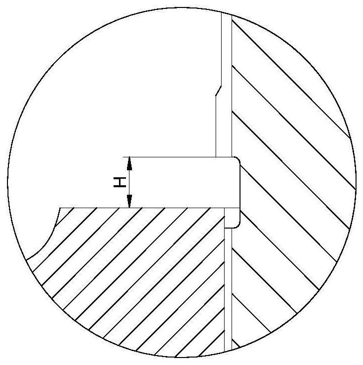
technical field [0001] The invention belongs to the technical field of detection equipment, and in particular relates to a groove width detection device after gears and gear shafts are assembled. Background technique [0002] like Figure 1 to Figure 4 As shown, at present, after the reducer gear (workpiece 1) and the intermediate shaft (workpiece 2) are assembled, it is necessary to detect the groove width H after the gear is assembled, and select a corresponding thickness of the circlip according to the groove width H. According to the processing tolerance of the gear and the intermediate shaft, as well as the assembly requirements, there are 9 to 12 kinds of circlips with different thicknesses for selection. However, the groove width H after assembly of the gear (workpiece 1) and the intermediate shaft (workpiece 2) is relatively narrow, limited by the shape of the workpiece, the measurement space is small, and it is difficult to directly measure the groove width after as...

Claims


Application Information

Patent Timeline
Patent Type & Authority Patents(China)
IPC IPC(8): G01B21/02
CPCG01B21/02
Inventor 王军王朝雨宋泽王继承
Owner 东风汽车零部件集团有限公司刃量具分公司
Learn More