Compressor, motor and stator mechanism thereof

A stator and rotor technology, applied in the field of compression equipment, can solve problems such as easy increase of iron loss, achieve the effect of avoiding deterioration of iron loss, simple and reasonable structural design, and guaranteed performance

Pending Publication Date: 2017-07-07
ZHUHAI GREE REFRIGERATION TECH CENT OF ENERGY SAVING & ENVIRONMENTAL PROTECTION
View PDF4 Cites 2 Cited by
  • Summary
  • Abstract
  • Description
  • Claims
  • Application Information

AI Technical Summary

Problems solved by technology

[0003] Based on this, it is necessary to provide a stator mechanism that can reduce the iron loss caused by compressive stress during the shrink fit in order to solve the problem that the current stator structure tends to increase iron loss during shrink fitting, and also provides a motors, and compressors containing the above motors

Method used


Image

  • Compressor, motor and stator mechanism thereof
  • Compressor, motor and stator mechanism thereof
  • Compressor, motor and stator mechanism thereof

Examples


Embodiment Construction

[0030] In order to make the purpose of the present invention, technical solutions and advantages clearer, the following examples are combined with Attached picture , the compressor, motor and stator mechanism of the present invention will be further described in detail. It should be understood that the specific embodiments described here are only used to explain the present invention, not to limit the present invention.

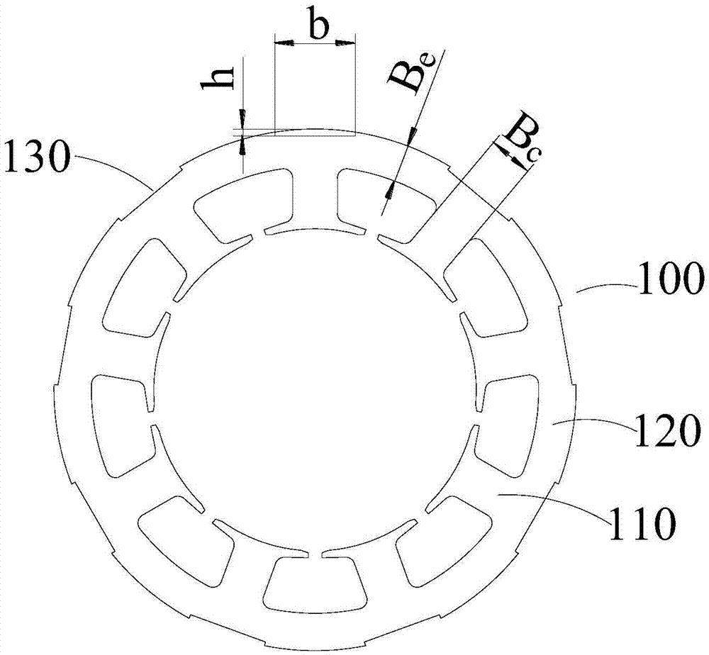
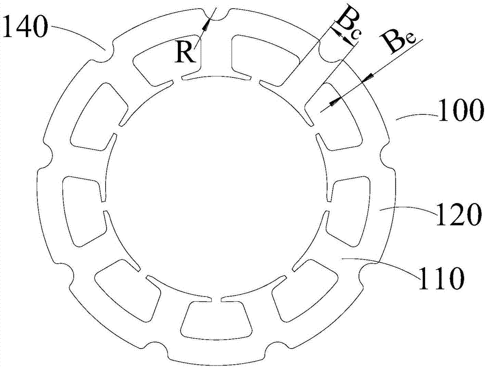
[0031] see picture , the present invention provides a stator mechanism 100 including a plurality of teeth 110 and a plurality of yokes 120 .

[0032] In the present invention, both the teeth 110 and the yoke 120 are punched from silicon steel sheets, the number of teeth 110 is equal to the number of yokes 120, and a plurality of teeth 110 and a plurality of yokes 120 are staggered and connected to form ring structure. That is, one tooth portion 110 is located between two adjacent yoke portions 120, and one yoke portion 120 is located between two adjacent...


PUM


Abstract

The invention provides a compressor, a motor and a stator mechanism thereof. The compressor, the motor and the stator mechanism thereof comprise multiple teeth and multiple yokes. The width of each tooth is Bc. The multiple teeth and the multiple yokes are arranged in a staggered manner and connected to form a ring structure. The width of each yoke is Be. The relationship between the width Bc of each tooth and the width Be of each yoke is as follows: 2*Bc/3<=Be<=Bc. The width of the yokes of the stator mechanisms is increased according to the stress distribution under shrinkage fit between the stator mechanism and a shell. Thus, the mean stress under shrinkage fit between the stator mechanism and the shell and the flux density amplitude of the yokes of the stator mechanism are reduced while the width of the yokes is increased. The iron loss of the motor is reduced under both effects. Deterioration of iron loss caused by compressive stress under shrinkage fit is avoided. The performance of the compressor is ensured.

Description

technical field [0001] The invention relates to the technical field of compression equipment, in particular to a compressor, a motor and a stator mechanism thereof. Background technique [0002] At present, the outer circle of most stator structures has more positioning holes and circulation holes, the number of positioning holes and circulation holes is equal to the number of stator teeth, and the positioning holes and circulation holes are located at the tops of the stator teeth. When the motor with the above-mentioned stator structure is used in a compressor, the stator structure and the housing need to be fixed by shrinking sleeves. There is a certain amount of interference between the stator structure and the housing. In order to ensure a certain holding force, the housing After the body is cooled, a certain compressive stress will be applied to the stator structure. The existence of this compressive stress will destroy the crystal lattice of the silicon steel sheet at ...

Claims


Application Information

Patent Timeline
Patent Type & Authority Applications(China)
IPC IPC(8): H02K1/14
CPCH02K1/146H02K2213/03
Inventor 曾学英周博孙文娇陈彬
Owner ZHUHAI GREE REFRIGERATION TECH CENT OF ENERGY SAVING & ENVIRONMENTAL PROTECTION
Why Eureka
Try Eureka