
Eureka
For R&D, Eureka makes reading and utilizing patents & technical documents easy.
Eureka AIR
Designed for self-driven R&D workflows. Generate viable solutions, solve complex R&D challenges, empower your innovation with AI.

Eureka Materials
Designed for material experts only. Revolutionize your material R&D, from search, analyze, to developing new materials.

TechResearch
Generate reliable direction feasibility study reports for your R&D in just a few steps.

TechSeek
Discover and master advanced knowledge NOW. Basics, ideas, possibilities, all at once.

TechMind
As an expert in R&D Theories, TechMind can generates customized viable solutions instantly.

TechRisk
Analyze your overall solution with one click, know your potential R&D risks in advance.

TechMonitor
Get weekly tech updates, stay abreast of the latest tech innovations and key insights.
Ink boxes and printing device
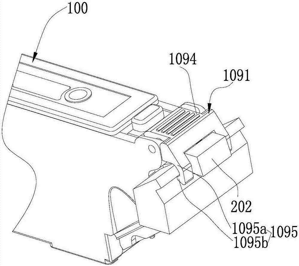
An ink cartridge and installation part technology, applied in the field of printing, can solve the problems such as damage or breakage of the connecting part 1095a, low reliability of the ink cartridge installation, and inability of the movable parts to be effectively engaged, so as to achieve the effect of ensuring reliability and preventing impact or damage.
- Summary
- Abstract
- Description
- Claims
- Application Information
AI Technical Summary
Problems solved by technology
Method used
Image

Examples
no. 1 example
[0089] Such as Figure 9-12 As shown, the main body 211 is rotatably connected to the concave portion 221, and the rotation axis of the main body 211 can be arranged in the concave portion 221. Specifically, the main body 22 of the ink cartridge can be provided with a shaft hole 222, and the main body 211 is provided with a movable part shaft 215, and the movable part shaft 215 is rotatably connected. In the shaft hole 222, the movable part shaft 215 is generally parallel to the X-axis. Certainly, the main body 22 of the ink cartridge may also be provided with a shaft of the movable part, and the main body 211 may be provided with a shaft hole. The above-mentioned structure realizes the engagement of the joint portion 213 and the installation portion 10 through the rotation of the body 211 , so as to facilitate the disassembly and installation of the ink cartridge 20 . The ink outlet 25 is located on the -Z axis side (lower part) of the ink cartridge main body 22 , and the mo...
no. 2 example
[0101] Such as Figure 13-14 As shown, the difference from the first embodiment is that the movable part 21 does not have a force receiving part, but the movable part 21 includes an operating part 28 connected to the body 211, and the operating part 28 is used for the operator to apply force , when it is necessary to take out the ink cartridge 20 from the installation part 10, the operator can push the operation part 28, and the movement of the operation part 28 can drive the movement of the joint part 213, that is, after the operation part is subjected to a force, it drives the movable part 21 around the axis of the movable part 215 rotates, so that the engaging portion 213 disengages from the protruding portion 15, and the ink cartridge 20 is taken out from the installation portion 10. Obviously, this way can facilitate the operator to take out the ink cartridge 20.
[0102] Generally, the operating part 28 is located on the side of the movable part 21 away from the bottom o...
no. 3 example
[0106] Such as Figure 15-18 As shown, the difference between the third embodiment and the first embodiment is that the main body 211 is slidably connected to the ink cartridge main body 211 along the joint portion 213 pointing to the direction of the ink cartridge main body 22, that is, in this embodiment, the movable part 21 is connected with the main body 211 The relative sliding of the main body 22 of the ink cartridge realizes the detachment of the ink cartridge 20 from the installation part 10 , and the sliding direction of the main body 211 is generally the direction of the X axis (including +X direction and −X direction).
[0107] Specifically, the main body 22 of the ink cartridge can be provided with a slide rail, and the body 211 is adapted to the slide rail, and it is slidably installed on the main body 22 of the ink cartridge along the direction of the X axis, such as Figure 15 As shown, the body 211 has a T-shaped structure along a section perpendicular to the X...
PUM
 Abstract
Description
Claims
Application Information
 - R&D Engineer
- R&D Manager
- IP Professional
- Industry Leading Data Capabilities
- Powerful AI technology
- Patent DNA Extraction
Browse by: Latest US Patents, China's latest patents, Technical Efficacy Thesaurus, Application Domain, Technology Topic, Popular Technical Reports.
© 2024 PatSnap. All rights reserved.Legal|Privacy policy|Modern Slavery Act Transparency Statement|Sitemap|About US| Contact US: help@patsnap.com