
Coil pipe type double-dryness flow dividing and heat exchange evaporator

A coil-type, thermal evaporation technology, applied in evaporators/condensers, lighting and heating equipment, refrigeration components, etc., can solve the problems of easy scaling on the outer wall of the coil, large flow pressure drop in the tube, and pressure loss in the tube, etc. Achieve the effect of improving overall heat exchange efficiency, saving consumables and energy, and reducing resistance and pressure drop

Active Publication Date: 2017-07-14
ZHONGKAI UNIV OF AGRI & ENG
View PDF6 Cites 0 Cited by
  • Summary
  • Abstract
  • Description
  • Claims
  • Application Information

AI Technical Summary

Problems solved by technology

Compared with other high-efficiency evaporators, ordinary coil evaporators have disadvantages such as low single-tube heat exchange efficiency, large flow pressure drop in the tube, and easy fouling on the outer wall of the coil. Therefore, it is sufficient to improve the thermal performance of the coil evaporator. engineering needs
In common coil evaporators, the heat transfer efficiency of the low-dryness working medium is low during the evaporation process of the heat exchange tube. The channel coil evaporator has the disadvantage of serious pressure loss in the tube

Method used


Image

  • Coil pipe type double-dryness flow dividing and heat exchange evaporator
  • Coil pipe type double-dryness flow dividing and heat exchange evaporator
  • Coil pipe type double-dryness flow dividing and heat exchange evaporator

Examples


Embodiment Construction

[0024] The present invention will be further described below in conjunction with the accompanying drawings and embodiments.

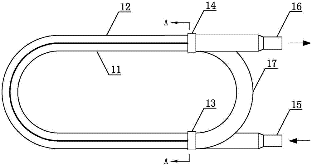
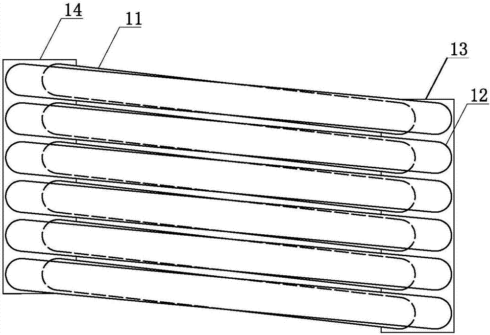
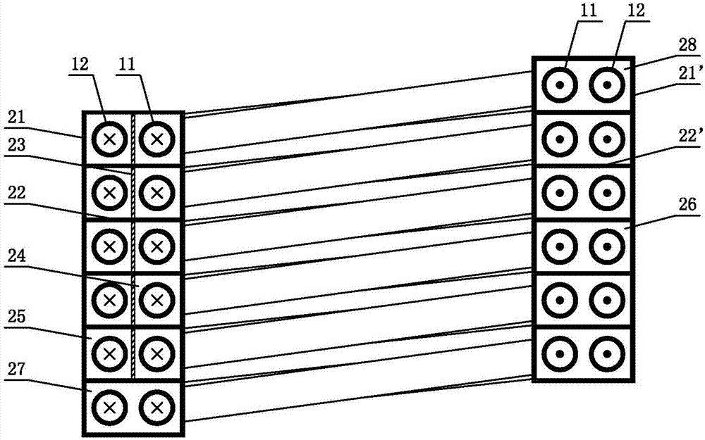
[0025] see Figure 1-Figure 9 , the coil-type double dryness split heat exchange evaporator includes six sets of interconnected heat exchange tube groups, the inlet end of the first heat exchange tube group is connected to the inlet pipe 15, and the outlet end of the tail group heat exchange tube group is connected to There is an outlet pipe 16, and the evaporating liquid is passed through the heat exchange tube group; specifically, the heat exchange tube group includes a high-quality heat exchange tube 11, a low-quality heat exchange tube 12 and a centrifugal shunt tube 17, wherein the centrifugal shunt The tube 17 is provided with a high dryness flow channel 34 and a low dryness flow channel 35, the side walls of the high dryness flow channel 34 and the side walls of the low dryness flow channel 35 communicate with each other; the high dryness flow ch...


PUM


Abstract

A coil pipe type double-dryness flow dividing and heat exchange evaporator comprises heat exchange pipe sets, an inlet pipe and an outlet pipe. Each heat exchange pipe set comprises a high-dryness heat exchange pipe, a low-dryness heat exchange pipe and a centrifugal flow dividing pipe. Each centrifugal flow dividing pipe is internally provided with a high-dryness runner and a low-dryness runner. The side wall of each high-dryness runner and the side wall of the corresponding low-dryness runner communicate with each other. The inlet end of each high-dryness heat exchange pipe communicates with the inlet pipe or the high-dryness runner in the last heat exchange pipe set. The inlet end of each low-dryness heat exchange pipe communicates with the inlet pipe or the low-dryness runner in the last heat exchange pipe set. The outlet end of each high-dryness heat exchange pipe communicates with the outlet pipe or the high-dryness runner in the next heat exchange pipe set. The outlet end of each low-dryness heat exchange pipe communicates with the outlet pipe or the high-dryness runner in the next heat exchange pipe set. The coil pipe type double-dryness flow dividing and heat exchange evaporator has the characteristics of being simple and reasonable in structure, excellent in performance, small in size, good in heat exchange effect, savable in energy, environmentally friendly, low in manufacturing cost, easy to produce and achieve, safe, reliable, high in practicability and the like.

Description

technical field [0001] The invention relates to an evaporator, in particular to a coil-type double dryness shunt heat exchange evaporator. Background technique [0002] Coil evaporators are widely used in the low-temperature concentration of food under vacuum conditions, as well as in the concentration of materials in the fields of medicine and chemical industry. The existing coil-type evaporator is mainly composed of heat exchange tube rows without external fins (some have fins). Compared with other high-efficiency evaporators, ordinary coil evaporators have disadvantages such as low single-tube heat exchange efficiency, large flow pressure drop in the tube, and easy fouling on the outer wall of the coil. Therefore, it is sufficient to improve the thermal performance of the coil evaporator. engineering needs. In common coil evaporators, the heat transfer efficiency of the low-dryness working medium is low during the evaporation process of the heat exchange tube. The chan...

Claims


Application Information

Patent Timeline
Patent Type & Authority Applications(China)
IPC IPC(8): F25B39/02F25B43/00
CPCF25B39/028F25B43/00
Inventor 丁力行钟天明秦颖恒吕金虎张平湖陈嘉澍邓玉艳沈向阳
Owner ZHONGKAI UNIV OF AGRI & ENG
Learn More