
Method for measuring sound intensity of pulse response signal

A technique of impulse response and signal, which is applied in measuring devices, measuring ultrasonic/sonic/infrasonic waves, instruments, etc., can solve the problems of inconspicuous physical characteristics and inconvenient impulse response noise intensity, etc., and achieve the effect of accurate judgment

Active Publication Date: 2017-07-14
东台城东科技创业园管理有限公司
View PDF9 Cites 0 Cited by
  • Summary
  • Abstract
  • Description
  • Claims
  • Application Information

AI Technical Summary

Problems solved by technology

When using the cross-spectrum method to calculate the sound intensity of the impulse response wave, the Fourier transform decomposes the impulse response signal into multiple sine and cosine signals of different frequencies, resulting in the dispersion of the sound intensity values ​​on the spectrum at multiple different frequency points. Negative sound intensity may even appear at some frequency points, and the measurement and calculation results reflect that the noise intensity of the impulse response is not simple enough, and the physical characteristics are not obvious

Method used


Image

  • Method for measuring sound intensity of pulse response signal
  • Method for measuring sound intensity of pulse response signal
  • Method for measuring sound intensity of pulse response signal

Examples


Embodiment

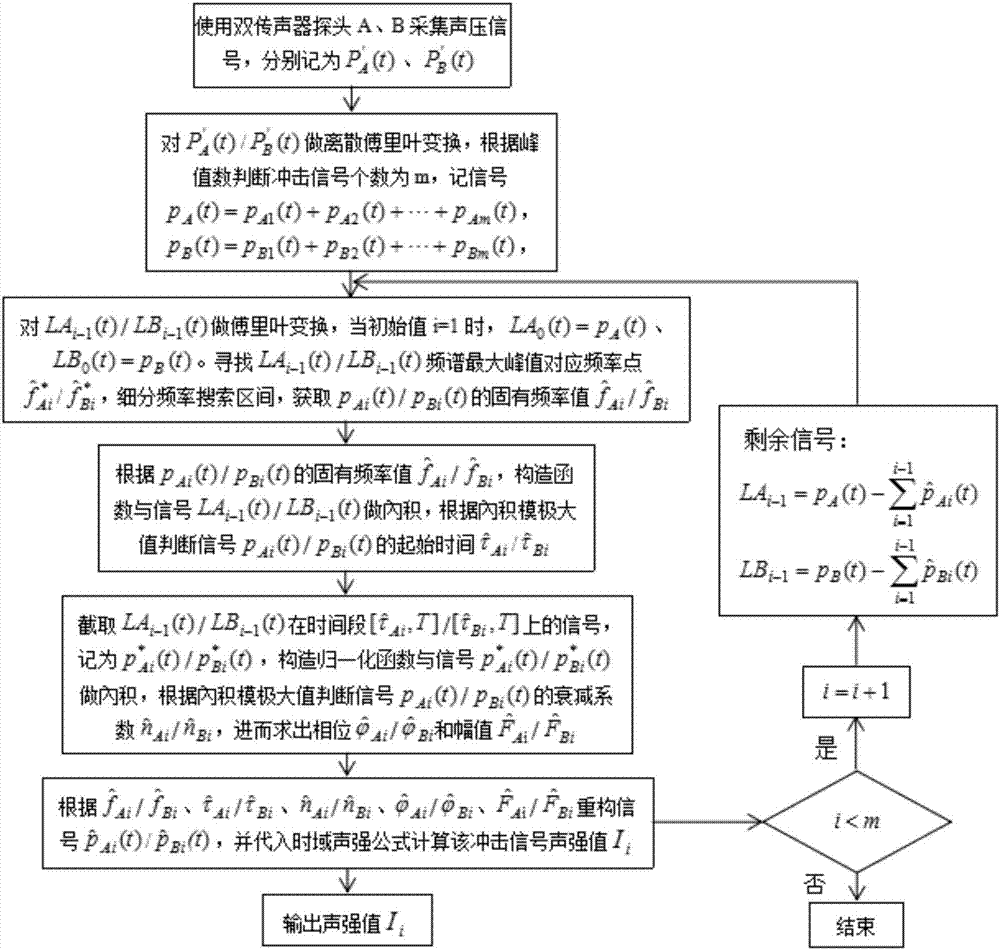
[0118] Example: such as figure 2 as shown,

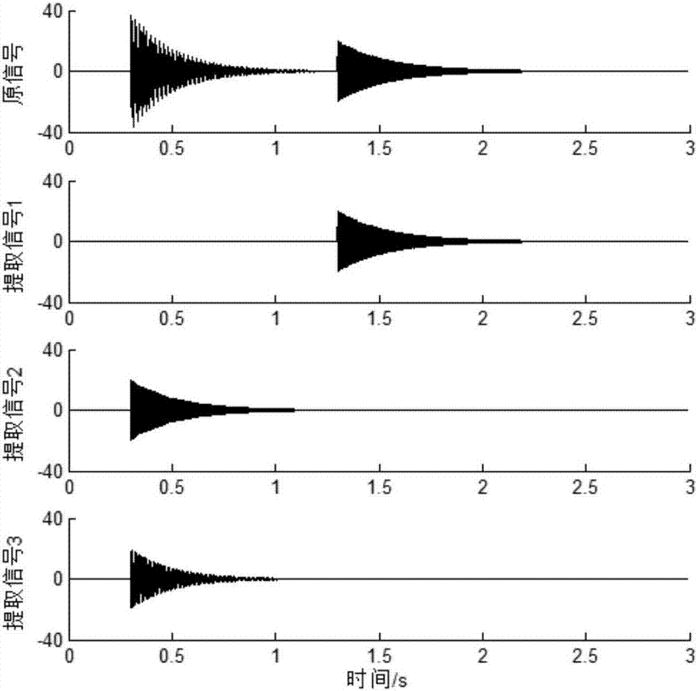
[0119] Suppose there is a plane acoustic wave consisting of 3 impulse response components:

[0120]

[0121] Among them, A i , n i , t i , f i , are the amplitude, attenuation coefficient, start time, natural frequency, and initial phase of the i-th (i=1, 2, 3) impulse response signal, respectively. See Table 1 for specific parameter values. Response signals 2, 3 occur simultaneously, and response signal 1 occurs later in time.

[0122] response signal Natural frequency(Hz) start time(s) Amplitude (pa) Attenuation coefficient phase signal 1 450.21 1.3 20 4.2 0.2 signal 2 250.82 0.3 20 4.6 0.2 signal 3 100.15 0.3 20 5.3 0.5

[0123] Table 1: Characteristic parameters of each impulse response acoustic signal

[0124] S01: Use dual-microphone probes A and B to collect the sound pressure data of the impulse response signal, and import the measured sound pressure data in...


PUM


Abstract

The invention provides a method for measuring sound intensity of a pulse response signal. The method comprises followings steps of using double microphone probes A, B to acquire sound pressure data of the pulse response signal, importing the sound pressure data measured by the probes into a computer and recording the sound pressure data as P'<A(t)>, P'<B(t)>; determining the fixed frequency value shown in the description of the pulse response signal pAi(t) and the fixed frequency value shown in the description of the pulse response signal pBi(t): according to the starting time, the fixed frequency, the attenuation coefficient, the amplitude value and the initial phase position, which are shown in the description, of the pulse response signal pAi(t), and the starting time, the fixed frequency, the attenuation coefficient, the amplitude value and the initial phase position, which are shown in the description, of the pulse response signal pBi(t), carrying out parameter reconstruction on the pulse response signals, and recording the obtained signals as shown in the description; and substituting the reconstructed pulse response signals shown in the description into an instant sound intensity calculation formula. According to the invention, the pulse response signals can be decomposed by extracting each pulse response signal from the original signal without use of the Fourier transform, and the sound intensity of each pulse response signal is calculated directly; the sound intensity value of each pulse response signal can be clearly measured and identified; and precise judgment of features of pulse response sound waves is facilitated.

Description

technical field [0001] The invention relates, in particular, to a method for measuring the sound intensity of an impulse response signal. Background technique [0002] Acoustic intensity characterizes the intensity of the acoustic energy. The sound intensity measurement method is widely used in sound power level calculation, vibration source identification and other fields. By observing the sound intensity value corresponding to each frequency point on the sound intensity spectrum, the engineer judges the actual sound energy contributed by each vibrating component, and then takes targeted noise reduction measures. Sound intensity measurement technology has always been a matter of concern. [0003] At present, the most commonly used sound intensity measurement method is the double-microphone cross-spectrum method. Fourier transform is the core step of the cross-spectrum method to measure sound intensity. p A (t), p B (t) transformed into frequency domain sound pressure s...

Claims


Application Information

Patent Timeline
Patent Type & Authority Applications(China)
IPC IPC(8): G01H17/00
Inventor 赵晓丹韩俊阳王琦
Owner 东台城东科技创业园管理有限公司
Learn More