Micro-nano fiber grating laser writing method and device

A technology of micro-nano optical fibers and optical fibers, which is applied in micro-lithography exposure equipment, photolithographic process exposure devices, cladding optical fibers, etc., can solve the problems of difficulty in obtaining sulfide optical fibers, fragile micro-nano fiber gratings, and complex fiber grating processes. , to achieve the effect of improving the writing efficiency, improving the visibility of the writing stripes, and reducing the cost

Inactive Publication Date: 2012-07-04
JINAN UNIVERSITY
View PDF2 Cites 25 Cited by
  • Summary
  • Abstract
  • Description
  • Claims
  • Application Information

AI Technical Summary

Problems solved by technology

The disadvantage is that the preparation of fiber gratings using femtosecond lasers is complex and costly. At the same time, the writing method of femtosecond lasers belongs to the quartz damage mechanism, which makes micro-nano fiber gratings very fragile and difficult to preserve.
Using this method, first of all, it is difficult to obtain sulfide optical fiber and the price is expensive; secondly, the structure of sulfide optical fiber is relatively special, and the core refractive index is as high as 2.7 (ordinary optical fiber is generally less than 1.5), so the fusion and coupling with the detection optical fiber is also the problem

Method used


Image

  • Micro-nano fiber grating laser writing method and device
  • Micro-nano fiber grating laser writing method and device
  • Micro-nano fiber grating laser writing method and device

Examples


Embodiment 1

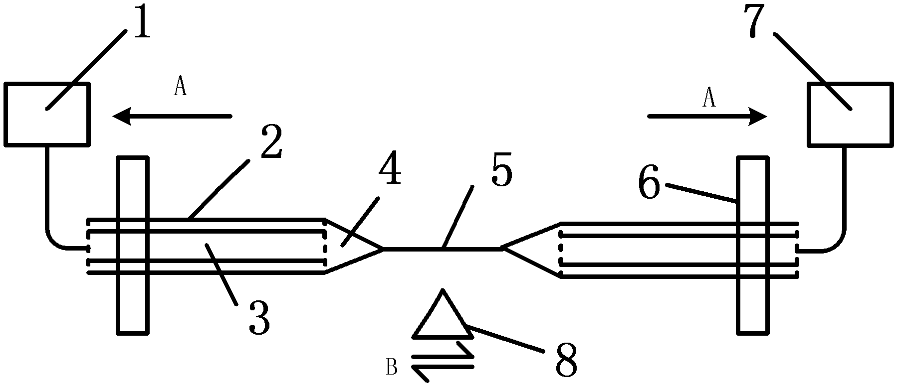
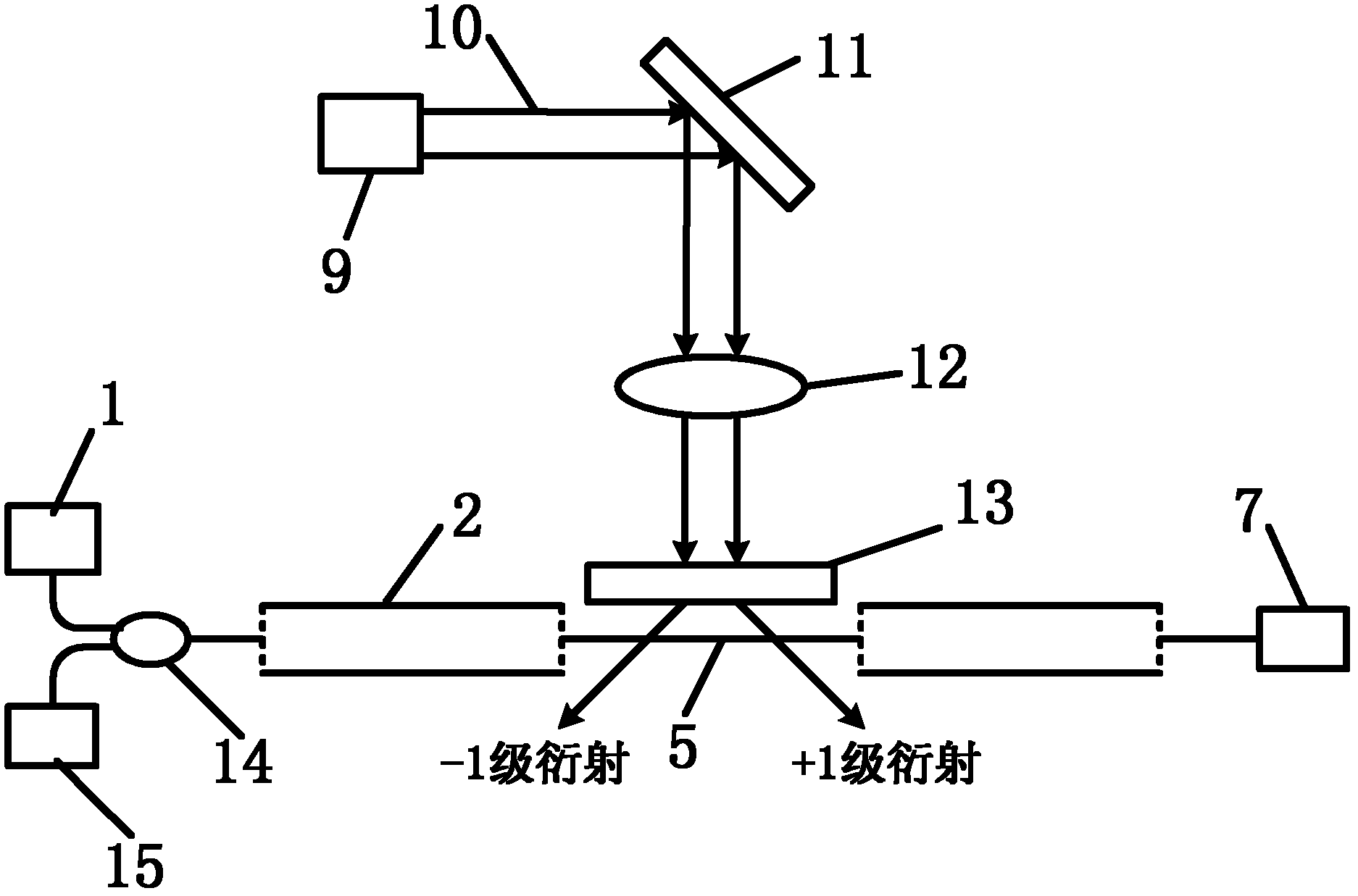
[0037] Such as figure 1As shown, a micro-nano fiber grating laser writing device that realizes the above method includes a fiber holder 6 and an ArF excimer laser 9 that emits 193nm ultraviolet laser light, a 45-degree full-power reflector 11, a cylindrical lens 12, The phase mask 13, the optical fiber after tapering is fixed on the optical fiber fixture 6, the micro-nano fiber zone 5 of the optical fiber is arranged in parallel in front of the phase mask 13, and the 193nm ultraviolet laser 10 emitted by the ArF excimer laser 9 passes through 45 degrees of full power After the reflector 11 is emitted, it shoots perpendicularly to the cylindrical lens 12 , and the phase mask 13 is arranged in front of the cylindrical lens 12 . Both ends of the fiber holder 6 are also provided with a broadband light source 1 and a spectrometer 7 respectively, and both are connected to the optical fiber. A visible red laser 15 is also connected to one end of the optical fiber, and the laser ligh...


PUM

PropertyMeasurementUnit
diameteraaaaaaaaaa
diameteraaaaaaaaaa
refractive indexaaaaaaaaaa

Abstract

The invention discloses a micro-nano fiber grating laser writing method and a micro-nano fiber grating laser writing device. The method comprises the following steps of: tapering normal multi-mode fibers; manufacturing micro-nano fibers; and then taking 193 nm ultraviolet laser as a scribing means. The device comprises a fiber clamp, and an ArF excimer laser, a 45-degree full power reflector, a cylindrical lens and a phase mask plate which are sequentially arranged, wherein the ArF excimer laser is used for emitting 193 nm ultraviolet laser; the tapered fiber is fixed on the fiber clamp; micro-nano fiber regions of the fibers are arranged in front of the phase mask plate in parallel; the 193 nm ultraviolet laser emitted by the ArF excimer laser is reflected through the 45-degree full power reflector and then vertically emitted to the cylindrical lens; and the phase mask plate is arranged in front of the cylindrical lens. According to the method and the device, extra processing for the fibers is not required, the mechanical strength and the toughness of the fibers are kept, the cost is low, the scribing efficiency is high, the bandwidth is narrow, the mode is controllable and the repeatability is high.

Description

technical field [0001] The invention relates to the research field of fiber grating writing methods, in particular to a micro-nano fiber grating laser writing method and device. Background technique [0002] As one of the most important photonic devices in the 20th century, fiber Bragg gratings (referred to as fiber gratings) have been widely used in the fields of optical fiber sensing and optical fiber communication due to their small size, high sensitivity, wavelength coding, and anti-electromagnetic interference. With the continuous development of optical fiber biomedical technology, many researchers have aimed at fiber grating devices as a new research direction for biosensing. However, the traditional fiber grating cannot use the evanescent field to interact with the outside world due to the thick cladding. Therefore, how to extend the application of fiber gratings in the detection direction of the refractive index of the external environment has become the focus and h...

Claims


Application Information

Patent Timeline
Patent Type & Authority Applications(China)
IPC IPC(8): G02B6/02G03F7/20B23K26/00B23K26/42B23K26/362B23K26/70
Inventor 关柏鸥冉洋金龙李杰
Owner JINAN UNIVERSITY
Why Eureka
Try Eureka