
Welding method of polarization-maintaining photonic crystal fiber

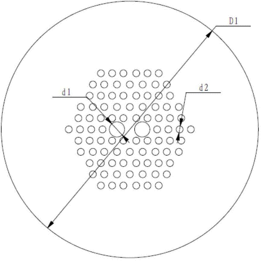
A technology of photonic crystal fiber and polarization-maintaining fiber, which is applied in the coupling of optical waveguide and other directions, can solve the problems of excessive fusion loss and achieve the effects of reducing fusion loss, reducing loss and reducing interference

Active Publication Date: 2014-03-26
BEIJING AEROSPACE TIMES OPTICAL ELECTRONICS TECH
View PDF4 Cites 6 Cited by
  • Summary
  • Abstract
  • Description
  • Claims
  • Application Information

AI Technical Summary

Problems solved by technology

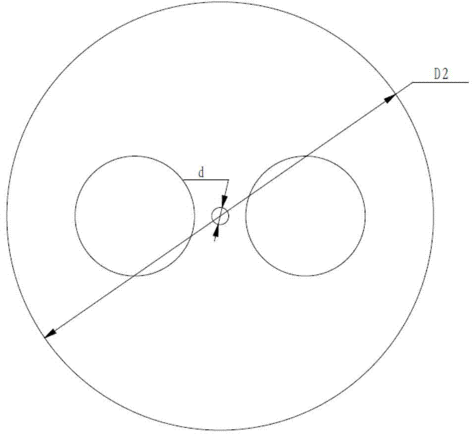
[0005] The problem solved by the technology of the present invention is: to overcome the deficiencies of the prior art, to provide a polarization-maintaining photonic crystal fiber fusion splicing method, which can effectively improve the alignment accuracy of the polarization axis, avoid the problem of excessive splice loss caused by the mismatch of the optical fiber mode field, and at the same time Has high welding strength

Method used


Image

  • Welding method of polarization-maintaining photonic crystal fiber
  • Welding method of polarization-maintaining photonic crystal fiber
  • Welding method of polarization-maintaining photonic crystal fiber

Examples


specific Embodiment approach

[0040]Step 1: Pretreating the ends of the two optical fibers to be fused, the pretreatment sequentially including heating, cleaning and cutting;

[0041] (1) Heating: Remove the bending and twisting of the optical fiber caused by external force. In this embodiment, place 8 cm of the end of the optical fiber to be fused in the heating tank of the fusion splicer, and heat for 15 seconds each;

[0042] (2) Cleaning: Put the optical fiber with the coating stripped off in an acetone solution for ultrasonic cleaning. In this embodiment, the ultrasonic cleaning time of the polarization-maintaining photonic crystal optical fiber in the acetone solution is 12s. If it is a stress-shaped polarization-maintaining fiber, the ultrasonic cleaning time in acetone solution is 30s;

[0043] (3) Cutting: Clamp one end of the two optical fibers to be fused with a clamp, and apply a tensile force F along the axial direction of the optical fiber, and then use a cutting knife to draw a cut at the en...


PUM


Abstract

The invention discloses a welding method of a polarization-maintaining photonic crystal fiber, and relates to fiber welding. The welding method comprises pretreating two fibers to be welded, wherein the pretreatment comprises heating, cleaning and cutting; putting the two fibers into a welding chamber of a welding machine, and aligning with a polarization shaft; preheating, reheating and cyclically heating welding parts, and strengthening and protecting welding points. According to the welding method of the polarization-maintaining photonic crystal fiber, the alignment accuracy of the polarization shaft is effectively improved, excessive welding loss caused by mismatching of fiber and mode field is avoided, and meanwhile the welding strength is high.

Description

technical field [0001] The invention relates to a polarization-maintaining photonic crystal fiber fusion splicing method. Background technique [0002] Photonic crystal fiber is a fiber with periodically arranged air holes in the cladding, also known as microstructure fiber or holey fiber, which can be divided into total internal reflection type and photonic bandgap type. Polarization-maintaining photonic crystal fiber introduces two large air holes into the cladding periodic structure to achieve high birefringence, thereby achieving the function of polarization maintenance. Due to the special structure and light guiding mechanism of photonic crystal fiber, it has the characteristics of high coupling efficiency, low bending loss, low nonlinearity, low dispersion and high birefringence that traditional core / clad structure fiber does not have. . [0003] When using photonic crystal fibers, it is inevitable to connect photonic crystal fibers to other types of fibers, or to ph...

Claims


Application Information

Patent Timeline
Patent Type & Authority Applications(China)
IPC IPC(8): G02B6/255
Inventor 李晶张智华尹其其杨学礼
Owner BEIJING AEROSPACE TIMES OPTICAL ELECTRONICS TECH
Learn More