
Image Synchronization Method Based on Computer Cluster Visualization System

A computer cluster and image synchronization technology, which is applied in the input/output process of computing and data processing, instruments, etc., can solve problems such as loss of synchronization, and achieve a good look and feel effect

Active Publication Date: 2020-02-14
GUANGDONG JITONG INFORMATION DEV CO LTD
View PDF5 Cites 0 Cited by
  • Summary
  • Abstract
  • Description
  • Claims
  • Application Information

AI Technical Summary

Problems solved by technology

[0005] Since each computer's processing (mainly rendering) of the small image is processed in an independent thread, it may be out of sync due to differences in network or node speeds

Method used


Image

  • Image Synchronization Method Based on Computer Cluster Visualization System
  • Image Synchronization Method Based on Computer Cluster Visualization System
  • Image Synchronization Method Based on Computer Cluster Visualization System

Examples


Embodiment 1

[0044] The invention relates to an image synchronization method based on a computer cluster visualization system, which is suitable for the computer cluster visualization system where a large-screen display composed of multiple electronic display screens is located.

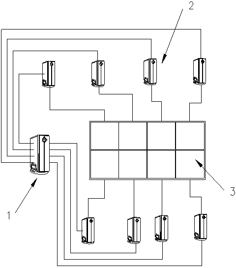
[0045] refer to figure 1 The computer cluster visualization system includes a master computer and a slave computer connected with the master computer, the slave computer is connected with an electronic display screen, and the master computer is connected with a display server. In this embodiment, 8 small electronic display screens constitute a 4*2 large display screen, and the computer is connected one-to-one with the small electronic display screens, and the number is also 8.

[0046] The host computer decodes the video obtained from the display server to obtain video images, and then corrects the video images by means of texture maps, so that each frame of video images can be taken out in real time to generate ...

Embodiment 2

[0054] An image synchronization method based on a computer cluster visualization system is applicable to a computer cluster visualization system where a projection wall composed of multiple projectors and projection cloth is located.

[0055] refer to image 3 , the computer cluster visualization system includes a master computer, a slave computer connected to the master computer, a projector connected to the slave computer, and a projection cloth assumed to be in front of the projector. In this embodiment, 8 projectors and 1 projection cloth form a projection wall. 8 slave computers are connected one-to-one with 8 projectors. The system also includes a digital camera connected to the host computer.

[0056] Due to the errors in the installation angle and orientation of the projectors, the pictures projected by each projector on the projection cloth will more or less have problems of not being connected and jumping.

[0057] Therefore, for a computer cluster visualization s...


PUM


Abstract

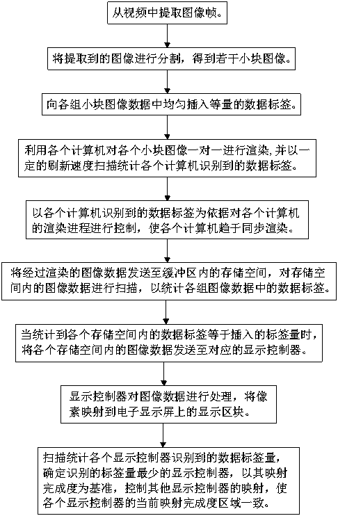
The invention discloses an image synchronization method based on a computer cluster visualization system. The method comprises the following steps that: inserting label data into the image data of each segmented small-block image; then, taking a data label as a reference to control the image rendering process of each computer to enable each computer to approach to synchronous rendering; taking the data label as the reference, checking the image data sent to a display control host to judge whether he image of each small-block image is completely transmitted to respectively corresponding display control host or not; and when data finishes being received, beginning to map the image data to a display screen by the display control host so as to guarantee that each small display screen can simultaneously display the image data. In addition, the data label is taken as the reference to control the mapping of each display control host, and therefore, the image data on each small display screen is synchronously mapped. Therefore, all small-block images on a large display screen can be free from hopping, transition is natural, and impression is good.

Description

technical field [0001] The present invention relates to the technical field of mosaic display, more specifically, it relates to an image synchronization method based on a computer cluster visualization system. Background technique [0002] With the development of science and technology, display devices emerge in an endless stream in the field of visualization. Various technologies will make display devices thinner, clearer, better in color, higher in brightness, and more energy-efficient, but it is certain that they will not The emergence of a single super-large display screen, even if it is technically possible, will cause the product to be extremely expensive due to high production costs and low demand, and it is difficult to promote this product to the market. Therefore, the current large-screen display technology usually splices multiple small screens together to form a super-large display, and each small display is responsible for displaying one area of ​​the super-larg...

Claims


Application Information

Patent Timeline
Patent Type & Authority Patents(China)
IPC IPC(8): G06F3/14
CPCG06F3/1438G06F3/1454
Inventor 文张斌
Owner GUANGDONG JITONG INFORMATION DEV CO LTD
Learn More