Unlock instant, AI-driven research and patent intelligence for your innovation.

switch

A switch and plunger technology, which is applied in the field of switches, can solve the problems of easy contact between contacts and misoperation, and achieve the effect of preventing misoperation and reliable contact.

Active Publication Date: 2019-01-18
ORMON CORP
View PDF6 Cites 0 Cited by
  • Summary
  • Abstract
  • Description
  • Claims
  • Application Information

AI Technical Summary

Problems solved by technology

However, if a spring with a small spring constant is used, the contacts are likely to come into contact with each other due to external vibrations, etc., and malfunctions may occur.

Method used


Image

  • switch
  • switch
  • switch

Examples


Embodiment Construction

[0029] Hereinafter, embodiments of the present invention will be described in detail with reference to the drawings.

[0030] 〔1. Outline of switch structure〕

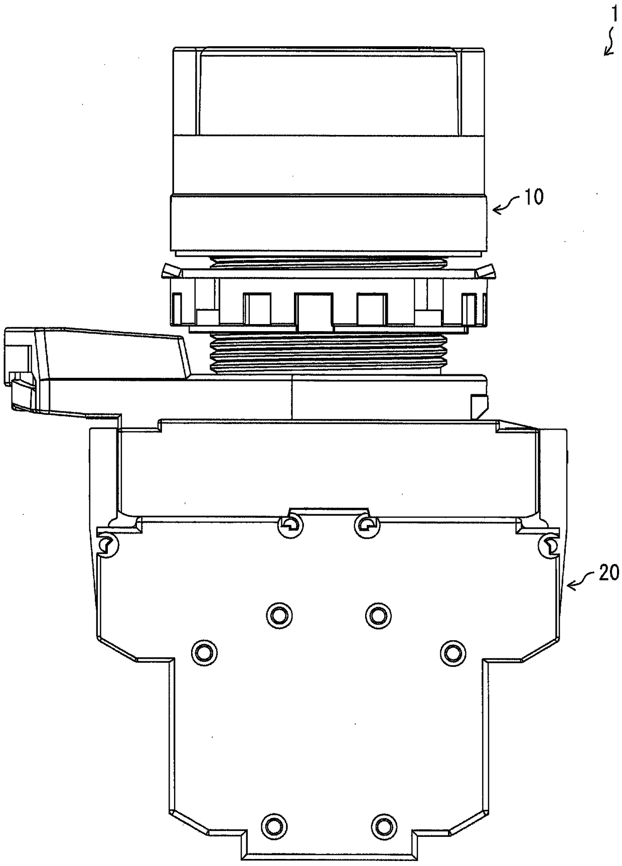
[0031] figure 1 It is a front view showing the appearance of the switch 1 according to the embodiment of the present invention. Such as figure 1 As shown, the switch 1 has an operation portion 10 and a body portion 20 .

[0032] The operation unit 10 is a member to be operated by an operator, and is provided so as to be able to perform a pressing operation on the main body unit 20 . In addition, in the present embodiment, a push button switch that is pressed by an operator is described, but the present invention is not limited thereto. For example, the switch 1 may have a cam mechanism for converting a rotation operation into a push operation, and the operation unit 10 may be configured to receive a rotation operation by an operator.

[0033] Figure 2A It is a perspective view showing the appearance of the main ...


PUM


Abstract

The present invention provides a switch capable of reliably contacting contacts with a small load and preventing malfunction. The switch (1) has a plunger (30) and a lower torsion spring (50) that changes according to the direction of movement of the plunger (30). When the plunger (30) is in the operating position, the lower torsion spring (50) The opposite direction of the reset direction exerts force on the plunger (30), and when the plunger (30) is at the reference position, the lower torsion spring (50) exerts force on the plunger (30) in a direction different from the opposite direction of the reset direction.

Description

technical field [0001] The present invention relates to switches. Background technique [0002] Conventionally, among switches that open and close contacts according to the movement of the plunger, a switch having a coil spring for returning the plunger is known. For example, Patent Document 1 discloses an emergency stop switch in which a coil spring is provided below the moving direction of the plunger. [0003] Patent Document 1: Japanese PCT Publication No. 2013-541145 (published on November 7, 2013) [0004] In a normally open switch in which the fixed contact on the side of the switch frame is in contact with the movable contact on the plunger side during operation, in order to make the contacts reliably contact during operation, it is required to make the contacts contact with a specified pressure . However, in the switch described in Patent Document 1, since the coil spring is compressed as the plunger moves, if the plunger movement amount increases, the compressio...

Claims


Application Information

Patent Timeline
Patent Type & Authority Patents(China)
IPC IPC(8): H01H13/26
CPCH01H13/26H01H2235/026H01H1/2025H01H1/502H01H3/022H01H13/503H01H1/221H01H3/38H01H3/60H01H13/52H01H2001/223
Inventor 胜部慎弥森田和明大塚博之
Owner ORMON CORP
Features
  • R&D
  • Intellectual Property
  • Life Sciences
  • Materials
  • Tech Scout
  • Unparalleled Data Quality
  • Higher Quality Content
  • 60% Fewer Hallucinations
Learn More