
Motor

A casing and rotor technology, which is applied in the direction of electrical components, electromechanical devices, electric components, etc., can solve problems such as large pressing force, inability to eliminate concentricity, and reduce service life of end covers, so as to improve service life, facilitate implementation, and simple structure Effect

Pending Publication Date: 2017-07-14
温州市飞扬电气有限公司
View PDF5 Cites 0 Cited by
  • Summary
  • Abstract
  • Description
  • Claims
  • Application Information

AI Technical Summary

Problems solved by technology

The stamping riveting process will cause damage to the motor end cover, thereby reducing the service life of the end cover
[0003] The motor end cover and the casing are clearance fit or interference fit. The clearance fit cannot eliminate the concentricity, and the pressing force is too large, which makes it difficult to assemble, resulting in serious deformation of the front and rear of the end cover and the casing.
Transition fit, either loose or tight, is difficult to achieve the desired effect

Method used

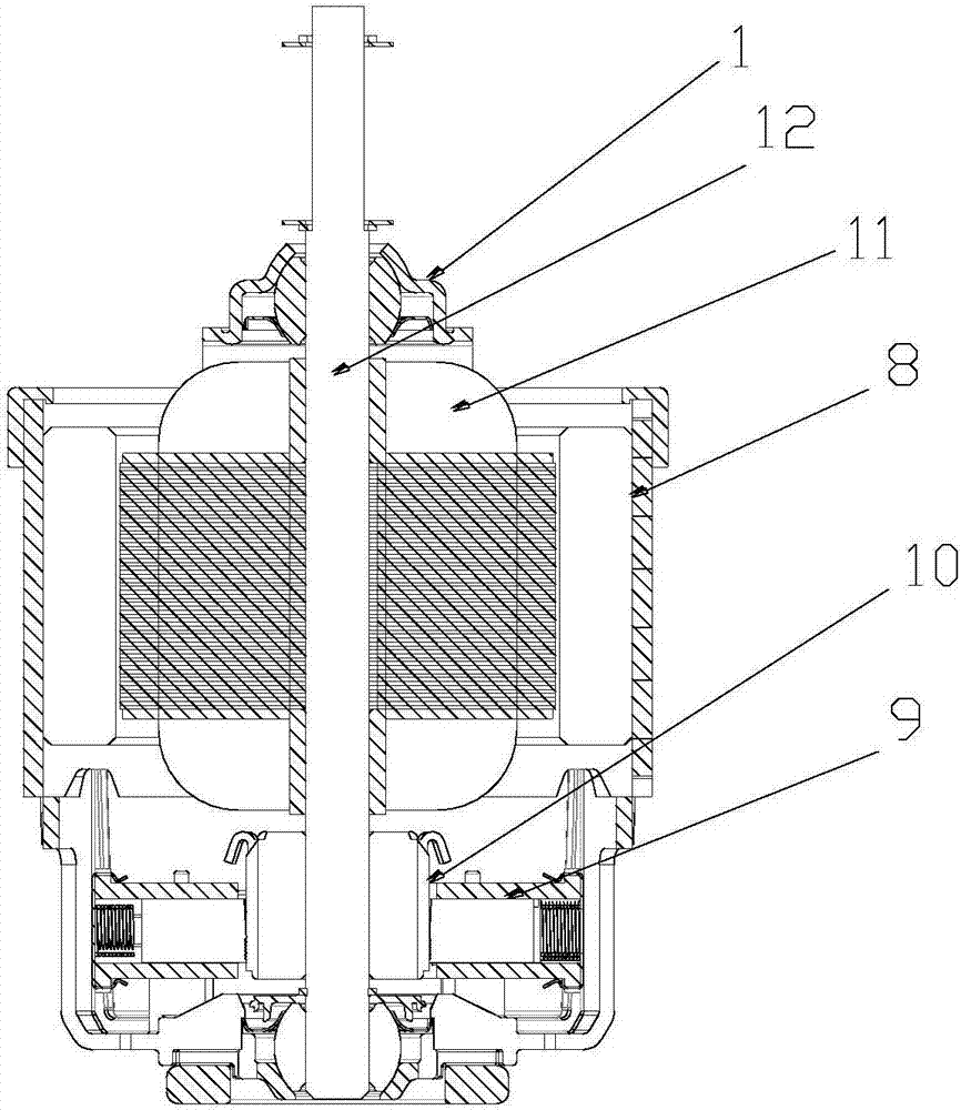
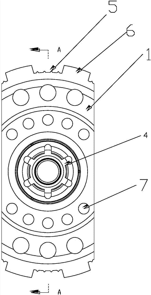
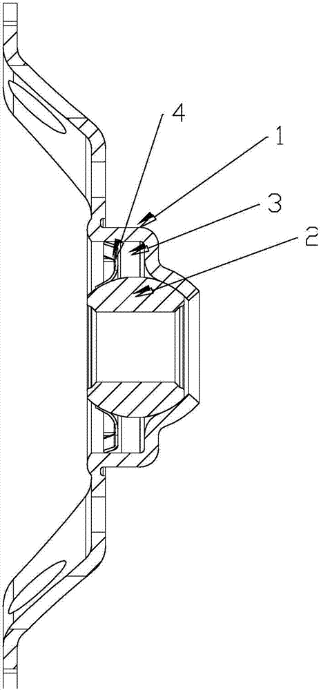

Image

  • Motor
  • Motor
  • Motor

Examples


Embodiment Construction

[0017] The specific implementation manner of the present invention will be described in detail below in conjunction with the accompanying drawings.

[0018] like Figure 1-3 As shown, a motor includes a housing 8, a carbon brush holder mechanism 9, a commutator 10, a stator and a rotor 11 are arranged in the housing 8, and the rotor 11 includes a The rotating shaft 12, the rotor chip is provided outside the rotating shaft 12, the rotor 11 is provided with coils, and the coils are respectively connected to the carbon brush holder mechanism through the commutator, and the upper and lower ends of the housing 8 are respectively provided with upper and lower ends Cover, the upper and lower end covers include an end cover with a stepped transition structure, a bearing 2 is matched on the inner side of the end face of the end cover, a felt ring 3 is set between the outer surface of the bearing 2 and the end cover, and a felt ring 3 is installed on the inner side of the bearing 2 An ...


PUM


Abstract

The invention belongs to the motor manufacturing technology field, and especially relates to a motor. The motor comprises a housing. A carbon brush holder mechanism, a commutator, a stator and a rotor are arranged in the housing. The rotor comprises a rotating shaft arranged in the housing. A rotor chip is arranged outside the rotating shaft. The rotor is provided with coils, and the coils are connected with the carbon brush holder mechanism through the commutator. A sawtooth structure is adopted to be in interference fit with the housing, thereby eliminating a gap between an end cap and the housing, and ensuring that the front and the rear of the end cap and the housing will not deform seriously. The inner rim and the outer rim of a cylindrical end cap bearing clamp are bent inwardly at the same time, and the circumference of the inner rim is evenly provided with multiple grooves, so that elastic deformation occurs during insertion, assembling is easy, and locking is firm. Therefore, the motor has a simple structure, is convenient to implement, and helps to prolong the service life of the end cap.

Description

technical field [0001] The invention belongs to the technical field of motor manufacturing, and in particular relates to a motor. Background technique [0002] In the existing motor end cover structure, the end cover and the bearing are riveted together by stamping. The stamping riveting process will cause damage to the motor end cover, thereby reducing the service life of the end cover. [0003] The motor end cover and the casing are clearance fit or interference fit. The clearance fit cannot eliminate the concentricity, and the pressing force is too large, which makes it difficult to assemble, resulting in serious deformation of the front and rear of the end cover and the casing. Transition fit, either loose or tight, is difficult to achieve the desired effect. [0004] Therefore, it is of great significance to study and design a motor end cover structure that is simple in structure, convenient to implement, and has a long service life. Contents of the invention [00...

Claims


Application Information

Patent Timeline
Patent Type & Authority Applications(China)
IPC IPC(8): H02K5/04H02K5/16H02K5/20
CPCH02K5/04H02K5/16H02K5/20
Inventor 冯志武陈皓楠陈俊周汉飞余强侯贵舟黄朝俊邓爱国
Owner 温州市飞扬电气有限公司
Learn More