
Five-degree-of-freedom magnetic suspension switched reluctance motor system and control method thereof

A technology of switched reluctance motors and reluctance motors, which is applied in the direction of AC motor control, control systems, and mechanical energy control, and can solve problems such as unfavorable system simplification and reliability, reduced suspension control accuracy, and increased suspension system control difficulty.

Active Publication Date: 2017-07-14
南京埃克锐特机电科技有限公司
View PDF4 Cites 5 Cited by
  • Summary
  • Abstract
  • Description
  • Claims
  • Application Information

AI Technical Summary

Problems solved by technology

[0003] The magnetic levitation switched reluctance motor is usually composed of a five-degree-of-freedom magnetic bearing and a switched reluctance motor. The traditional permanent magnet bias magnetic bearing requires a large thrust plate, which will cause large eddy current loss and temperature rise; while the traditional cone The shape electric excitation magnetic bearing has more control objects, and the axial suspension force is related to the square of the control winding current, which is not conducive to the simplification and reliability of the system
There is a strong coupling between the suspension forces, which also increases the difficulty of the control of the suspension system, and the accuracy of the suspension control is also reduced.
[0004] In addition, the motor and the magnetic bearing control system in the traditional magnetic levitation switched reluctance motor system are independent, and the integration degree is not high

Method used


Image

  • Five-degree-of-freedom magnetic suspension switched reluctance motor system and control method thereof
  • Five-degree-of-freedom magnetic suspension switched reluctance motor system and control method thereof
  • Five-degree-of-freedom magnetic suspension switched reluctance motor system and control method thereof

Examples


Embodiment Construction

[0066] The technical scheme of a five-degree-of-freedom magnetic levitation switched reluctance motor system and control method of the present invention will be described in detail below in conjunction with the accompanying drawings:

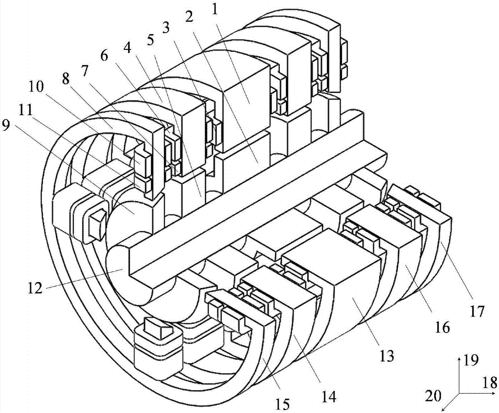
[0067] Such as figure 1 Shown is a three-dimensional structural schematic diagram of an embodiment of a five-degree-of-freedom magnetic levitation switched reluctance motor system embodiment of the present invention, wherein, 1 is a reluctance motor stator, 2 is a reluctance motor rotor, 3 is a reluctance motor coil, and 4 is a radial stator , 5 is the radial rotor, 6 is the radial bias coil, 7 is the radial suspension coil, 8 is the tapered stator, 9 is the tapered rotor, 10 is the axial bias winding, 11 is the axial suspension coil, 12 is the rotating shaft, 13 is the switched reluctance motor, 14 is the radial magnetic bearing Ⅰ, 15 is the tapered magnetic bearing Ⅰ, 16 is the radial magnetic bearing Ⅱ, 17 is the tapered magnetic bearing Ⅱ, 1...


PUM


Abstract

The invention discloses a five-degree-of-freedom magnetic suspension switched reluctance motor system and a control method thereof. The system comprises a switched reluctance motor, two radial magnetic bearings and two conical magnetic bearings, wherein one of the two radial magnetic bearings and one of the two conical magnetic bearings are arranged at one side of the switched reluctance motor, the other radial magnetic bearing and the other conical magnetic bearing are arranged at the other side of the switched reluctance motor, bias windings of the four magnetic bearings are connected in series to form a set of bias winding, four diodes are connected in series to a DC bus of an armature winding power circuit of the switched reluctance motor, the rotation control is same as a control mode of a traditional switched reluctance motor, suspension forces in five directions are only relevant to a bias current and a current of a suspension winding in each direction and are decoupled to one another, moreover, the current of the bias winding is only relevant to a current of a three-phase armature, no independent control is performed, and torques and the suspension forces can be controlled in a decoupling way. The motor system is high in integration, simple in winding structure, low in control variable and simple in suspension control, and a power converter is low in cost.

Description

technical field [0001] The invention relates to a five-degree-of-freedom magnetic levitation switched reluctance motor system and a control method thereof, and belongs to the technical field of magnetic levitation switched reluctance motors and control thereof. Background technique [0002] The magnetic levitation switched reluctance motor not only has the advantages of no friction and no lubrication of the magnetic bearing, but also inherits the high-speed adaptability of the switched reluctance motor and meets the harsh working environment. It has unique characteristics in aerospace, flywheel energy storage and military applications. Advantage. [0003] The magnetic levitation switched reluctance motor is usually composed of a five-degree-of-freedom magnetic bearing and a switched reluctance motor. The traditional permanent magnet bias magnetic bearing requires a large thrust plate, which will cause large eddy current loss and temperature rise; while the traditional cone ...

Claims


Application Information

Patent Timeline
IPC IPC(8): H02K7/09H02K29/00H02P25/08H02N15/00
CPCH02K7/09H02K29/00H02N15/00H02P25/08
Inventor 刘泽远蔡骏赵春文
Owner 南京埃克锐特机电科技有限公司
Features
  • Generate Ideas
  • Intellectual Property
  • Life Sciences
  • Materials
  • Tech Scout
  • Unparalleled Data Quality
  • Higher Quality Content
  • 60% Fewer Hallucinations
Learn More