Delivery aiding brisk walking machine with fetal position regulating function
A technology of fetal position and limit mechanism, which is applied in the direction of training equipment for adjusting coordination, training equipment for adjusting cardiovascular system, gymnastics equipment, etc. The effect of promoting natural childbirth and increasing capacity
- Summary
- Abstract
- Description
- Claims
- Application Information
AI Technical Summary
Problems solved by technology
Method used
Image
Examples
Embodiment 1
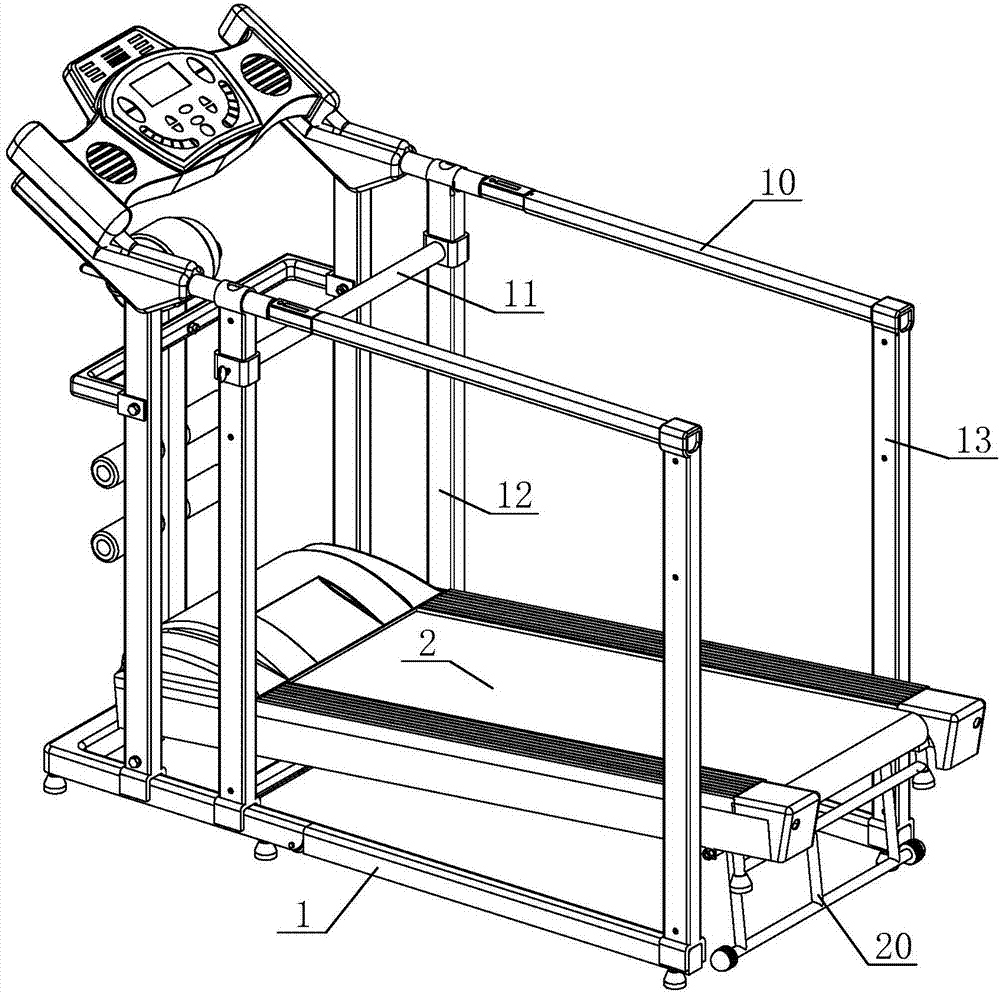
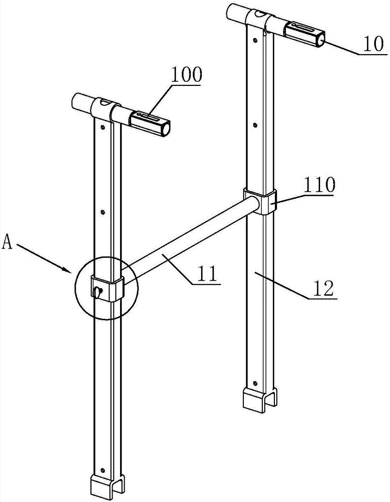
[0044] Such as Figures 1 to 3 A midwifery fast walking machine for adjusting the fetal position is shown, which includes a running belt device 2, a base 1 and an operation panel. The running belt device 2 is arranged to be inclined downward toward the front end of the operation panel. The pole 10 is arranged horizontally, the side lying pole 10 is fixed on the base 1 , and the side lying pole 10 is located on both sides of the running belt device 2 .
[0045] When using, refer to Figure 4 and Figure 5 , the puerpera supports her upper body with both hands on the side lying rod 10, while the upper body leans forward, and her legs step on the inclined running belt device 2, an angle that is conducive to natural childbirth is formed between the upper body and the lower body, and the puerpera always maintains This action is walking fast on a fast-walking machine.
[0046] The speed regulating button 100 is arranged on the side lying bar 10, which is convenient for the puerpe...
Embodiment 2
[0055] This embodiment is based on Embodiment 1, and a pulling rod 15 is added on the side lying rod 10. The height of the pulling rod 15 is higher than that of the side lying rod 10. The angle between them, so its height is higher to adapt to the usage habits of different mothers.
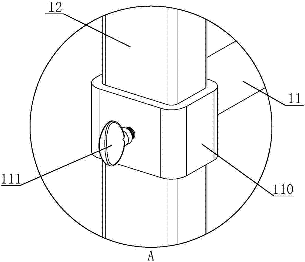
[0056] The pull rod 15 is fixed above the side-lying rod 10 through two second stop rods 14, the two ends of the pull rod 15 are provided with sleeves 110, the sleeves 110 are sleeved on the second stop rod 14, the sleeves 110 and A second limiting mechanism is provided between the second limiting rods 14 . The structure of the second limiting mechanism is the same as that of the first limiting mechanism in Embodiment 1, and the limiting bolt 111 in the second limiting mechanism presses against the surface of the second limiting rod 14 .
[0057] Such as Figure 9 As shown, in this embodiment, the second limit rod 14 and the side lying rod 10 are detachably plugged in. Below the second stop bar...
PUM
 Abstract
Description
Claims
Application Information
 - R&D
- Intellectual Property
- Life Sciences
- Materials
- Tech Scout
- Unparalleled Data Quality
- Higher Quality Content
- 60% Fewer Hallucinations
Browse by: Latest US Patents, China's latest patents, Technical Efficacy Thesaurus, Application Domain, Technology Topic, Popular Technical Reports.
© 2025 PatSnap. All rights reserved.Legal|Privacy policy|Modern Slavery Act Transparency Statement|Sitemap|About US| Contact US: help@patsnap.com


