Delivery assisting device for obstetrical department
An auxiliary device and obstetrical technology, applied in dentistry, dental chairs, medical science, etc., can solve the problems of not being able to meet the delivery needs of different puerperas, functional limitations, etc., and achieve the effect of wide application range and reducing odor
- Summary
- Abstract
- Description
- Claims
- Application Information
AI Technical Summary
Problems solved by technology
Method used
Image
Examples
Embodiment 1
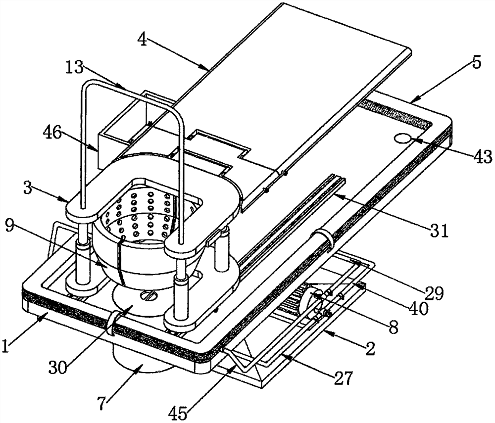
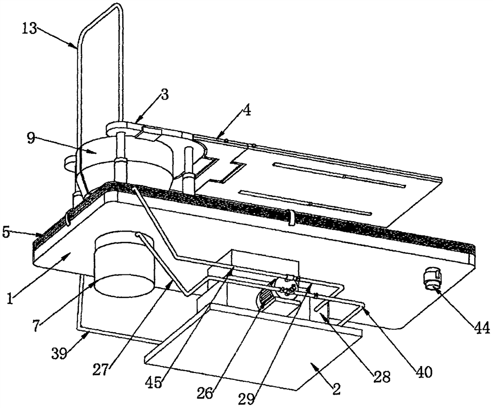
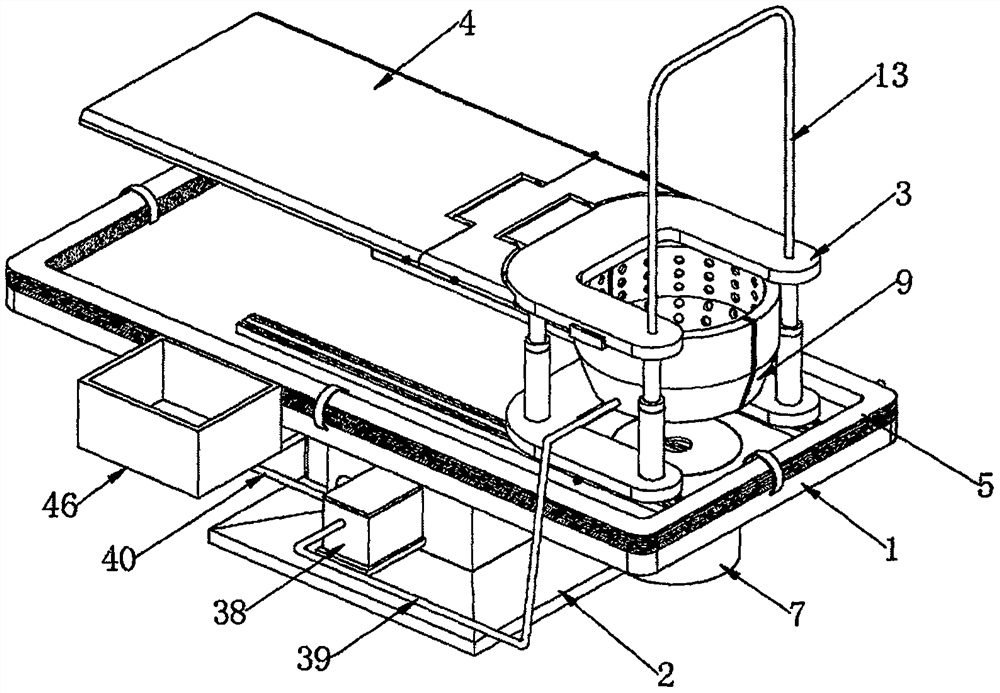
[0044] Refer to the manual attached Figure 1-8 , An obstetric aid device for obstetrics in this embodiment includes a horizontal plate 1 and a lifting base 2 arranged at the center of the bottom end of the horizontal plate 1. The lifting base 2 adopts the lifting structure on the existing delivery chair, and the lifting base 2 in the present invention The electrical equipment adopts the control method of the prior art, and will not be further described here. A birthing stool 3 is arranged on the front side of the top of the horizontal plate 1, and a backrest 4 is arranged at the rear end of the birthing stool 3. The birthing stool 3 includes a U-shaped upper and lower distribution. The seat plate 10 and the U-shaped bottom plate 11 are connected by four first telescopic rods 12, and the structure of the first telescopic rod 12 is a common technology, and will not be further described here. A handrail 13 is fixed on the front side of the top of the seat plate 10, so that the m...
Embodiment 2
[0053] Refer to the manual attached Figure 1-3 , 10, 11, 15, the top of the horizontal plate 1 is fixedly provided with two rails 31 distributed left and right, the tops of the two rails 31 are slidably provided with sliders 32, and the sides of the two sliders 32 away from each other are provided with a third The third bolt passes through the slider 32 and contacts one side of the rail 31. The two rails 31 are respectively arranged on both sides of the through hole 6, the two rails 31 are both arranged inside the airbag 5, and the two sliders 32 are respectively fixed Located on both sides of the bottom end of the U-shaped bottom plate 11 , the delivery stool 3 can move along the track 31 , which is convenient for adjusting the position of the delivery stool 3 .
[0054] A cover plate 30 is arranged inside the through hole 6 , the cover plate 30 is connected with the through hole 6 by screws, and a sealing ring 25 is arranged between the cover plate 30 and the through hole 6...
Embodiment 3
[0059] Refer to the manual attached Figure 1-3 , 7-11, there is a collection mechanism 7 below the through hole 6, the collection mechanism 7 is arranged on the front side of the bottom end of the horizontal plate 1, the collection mechanism 7 includes a collection bucket 23, the collection bucket 23 is arranged under the through hole 6, and the bottom of the through hole 6 The end is provided with a connecting ring 24, the top of the connecting ring 24 is fixed on the bottom end of the horizontal plate 1, the collecting bucket 23 is arranged at the bottom of the connecting ring 24 and the top of the collecting bucket 23 extends into the interior of the connecting ring 24 and is connected with the inner wall of the connecting ring 24 by threads, The threaded connection is convenient for disassembly and cleaning of the collecting bucket 23 .
[0060] The intake end of the air pump 26 is connected with a first suction pipe 27 , and one end of the first suction pipe 27 away from...
PUM
 Abstract
Description
Claims
Application Information
 - R&D
- Intellectual Property
- Life Sciences
- Materials
- Tech Scout
- Unparalleled Data Quality
- Higher Quality Content
- 60% Fewer Hallucinations
Browse by: Latest US Patents, China's latest patents, Technical Efficacy Thesaurus, Application Domain, Technology Topic, Popular Technical Reports.
© 2025 PatSnap. All rights reserved.Legal|Privacy policy|Modern Slavery Act Transparency Statement|Sitemap|About US| Contact US: help@patsnap.com


