Position adjustment device and circular die-cutting equipment

An adjustment device and an adjusted technology, which is applied in metal processing and other directions, can solve the problems of reducing the amount of cutting, keeping the surface of the knife edge line parallel to the surface of the product, affecting the time of cutting and closing time, etc., to achieve convenient operation and simple structure. Effect

Inactive Publication Date: 2019-03-19
XUYOU ELECTRONICS MATERIAL TECH (WUXI) CO LTD +2
View PDF8 Cites 0 Cited by
  • Summary
  • Abstract
  • Description
  • Claims
  • Application Information

AI Technical Summary

Problems solved by technology

However, due to repeated collisions between the ejector rod 3 and the force transmission hammer 51, the ejector rod 3 and the force transmission hammer 51 will have certain wear and deformation, which will lead to a reduction in the amount of knife output, and affect the time (speed) and retraction of the knife Time (speed), which affects the cutting quality
In addition, because the existing rotary die-cutting equipment is affected by the processing of the cutter, cutter roller 3' and pressure roller, assembly accuracy and transmission system, it is difficult for the blade line of the cutter to be parallel to the surface of the product, and it is also difficult to align with the Pressure roller surfaces remain parallel
In this way, the tool will inevitably be subjected to inconsistent force when cutting, which will not only cause local wear too fast, but also cause local cutting depth to be insufficient, or local cutting too deep and hard contact with the surface of the pressure roller, thereby accelerating tool wear and affecting cutting quality.
[0004] To sum up, in the existing rotary die-cutting equipment, the output of the cutter 52 of the cutter drum 5 usually needs to be guaranteed by improving the processing and assembly accuracy of the cutter. After the new cutter is installed on the machine, it often occurs The problem of unstable cutting quality is also not conducive to online adjustment of cutting process

Method used


Image

  • Position adjustment device and circular die-cutting equipment
  • Position adjustment device and circular die-cutting equipment
  • Position adjustment device and circular die-cutting equipment

Examples


Embodiment Construction

[0036] Specific embodiments of the present invention will be described in detail below in conjunction with the accompanying drawings. It should be understood that the specific embodiments described here are only used to illustrate and explain the present invention, and are not intended to limit the present invention.

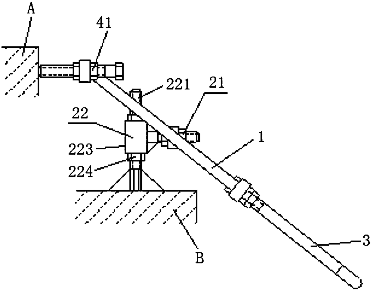
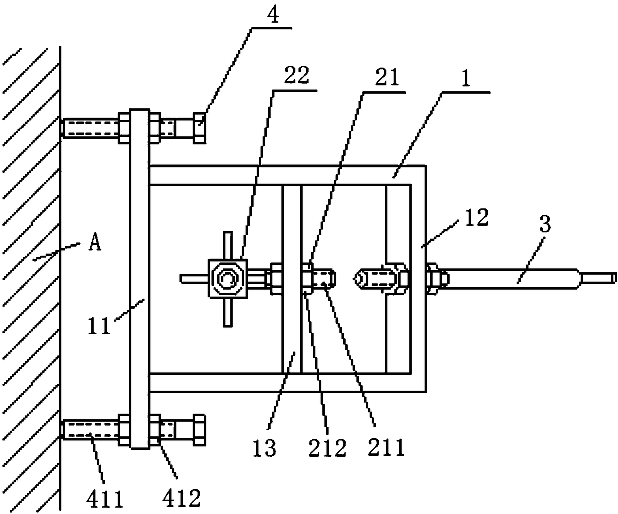
[0037] figure 1 and figure 2 A schematic structural view of the position adjustment device provided according to the present invention is shown. combine figure 1 and figure 2 As shown, the position adjustment device includes: an adjustment frame 1 and an adjustment mechanism connected with the adjustment frame 1 . Wherein, the adjustment frame 1 includes an inclined portion for pressing against the object to be adjusted, the plane where the inclined portion is located is always at a fixed angle to the horizontal direction, and the adjustment mechanism can drive the adjustment frame 1 to move in a direction parallel to the horizontal direction or perpendi...


PUM


Abstract

The invention relates to the technical field of column to column die cutting machines, and discloses a position adjusting device and column to column die cutting equipment. The position adjusting device comprises an adjusting frame (1) and an adjusting mechanism connected with the adjusting frame (1), wherein the adjusting frame (1) comprises an oblique part used for abutting against an adjusted object, a constant angle always exists between a plane where the oblique part is located and the horizontal direction, and the adjusting mechanism can drive the adjusting frame (1) to move in the direction of being parallel to the horizontal direction or perpendicular to the horizontal direction to achieve position adjusting, so that when the adjusting frame (1) abuts against the adjusted object, the adjusted object is adjusted along with movement of the adjusting frame (1). By means of the position adjusting device, on-line adjustment on cutters in the column to column die cutting equipment can be achieved, the cutters can be used more smoothly and accurately, and therefore the cutting quality is improved.

Description

technical field [0001] The invention relates to the technical field of rotary die-cutting machines, in particular to a position adjustment device and rotary die-cutting equipment. Background technique [0002] Rotary die-cutting equipment is widely used in various industries due to its advantages of fast die-cutting speed and low cost. Especially printing industry, electronics industry, health industry, etc. Both the cutter roller and the pressure roller of the rotary die-cutting equipment are cylindrical. When working, the feed roller sends the product to be cut to between the cutter roller and the pressure roller, and the two will transfer the product to be cut. Clamping and pressing against the roller mold, the cutter roller completes one working cycle every time it rotates. Due to the continuous rotation of the roller and less downtime, the rotary die-cutting equipment can produce continuously and have high production efficiency, especially suitable for mass production...

Claims


Application Information

Patent Timeline
Patent Type & Authority Patents(China)
IPC IPC(8): B26F1/38B26D7/26
CPCB26D2007/2664B26F1/38
Inventor 伍志寰
Owner XUYOU ELECTRONICS MATERIAL TECH (WUXI) CO LTD
Why Eureka
Try Eureka