Novel high-temperature high-pressure regulation valve

A high temperature and high pressure, regulating valve technology, applied in the direction of sliding valve, valve details, valve device, etc., can solve the problems of high pressure bypass valve not meeting the requirements of unit operation, frequent valve maintenance, and heavy maintenance workload, etc., and achieve surfacing welding. And grinding is convenient and easy, the quality is easy to ensure, and the effect of reducing erosion damage

Pending Publication Date: 2020-08-04
YICHUAN TECH CHENGDU CO LTD
View PDF0 Cites 0 Cited by
  • Summary
  • Abstract
  • Description
  • Claims
  • Application Information

AI Technical Summary

Problems solved by technology

Since my country began to gradually introduce subcritical, supercritical, and ultra-supercritical units in the 1990s, and the single-unit capacity has ranged from 300MW, 600MW to 1000MW and other large-scale power generation devices, my country has gone through the process of overall introduction and domestic imitation. The overall technology in this field The level has been greatly improved, but both imported and domestic high-pressure bypass valves are far from meeting the requirements of unit operation
[0003] The existing control valves, whether imported or domestic imitated high-pressure bypass valves, generally have internal leakage problems, which make the valves frequently overhauled and quickly internally leaked. Warm water cools the pipeline behind the valve to ensure that the temperature behind the valve is within a safe range, thereby ensuring the safe operation of the unit. The maintenance workload is heavy, the operating cost is high, and there is a great potential safety hazard. Although the imported products have different structures, There are also continuous improvements, but they have not been able to solve the fundamental problems in the structural principle, so the internal leakage is still
Most of the domestic products are imitations, and there is the same problem of internal leakage. Therefore, the present invention proposes a new type of high temperature and high pressure regulating valve

Method used


Image

  • Novel high-temperature high-pressure regulation valve
  • Novel high-temperature high-pressure regulation valve
  • Novel high-temperature high-pressure regulation valve

Examples


Embodiment Construction

[0025] The following will clearly and completely describe the technical solutions in the embodiments of the present invention with reference to the accompanying drawings in the embodiments of the present invention. Obviously, the described embodiments are only some, not all, embodiments of the present invention. Based on the embodiments of the present invention, all other embodiments obtained by persons of ordinary skill in the art without making creative efforts belong to the protection scope of the present invention.

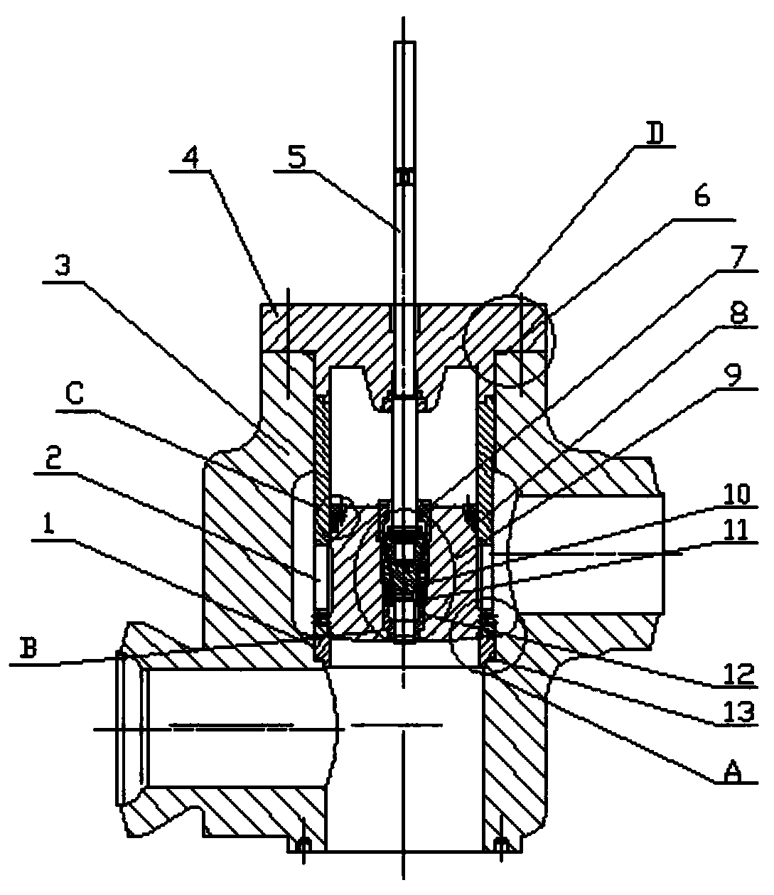
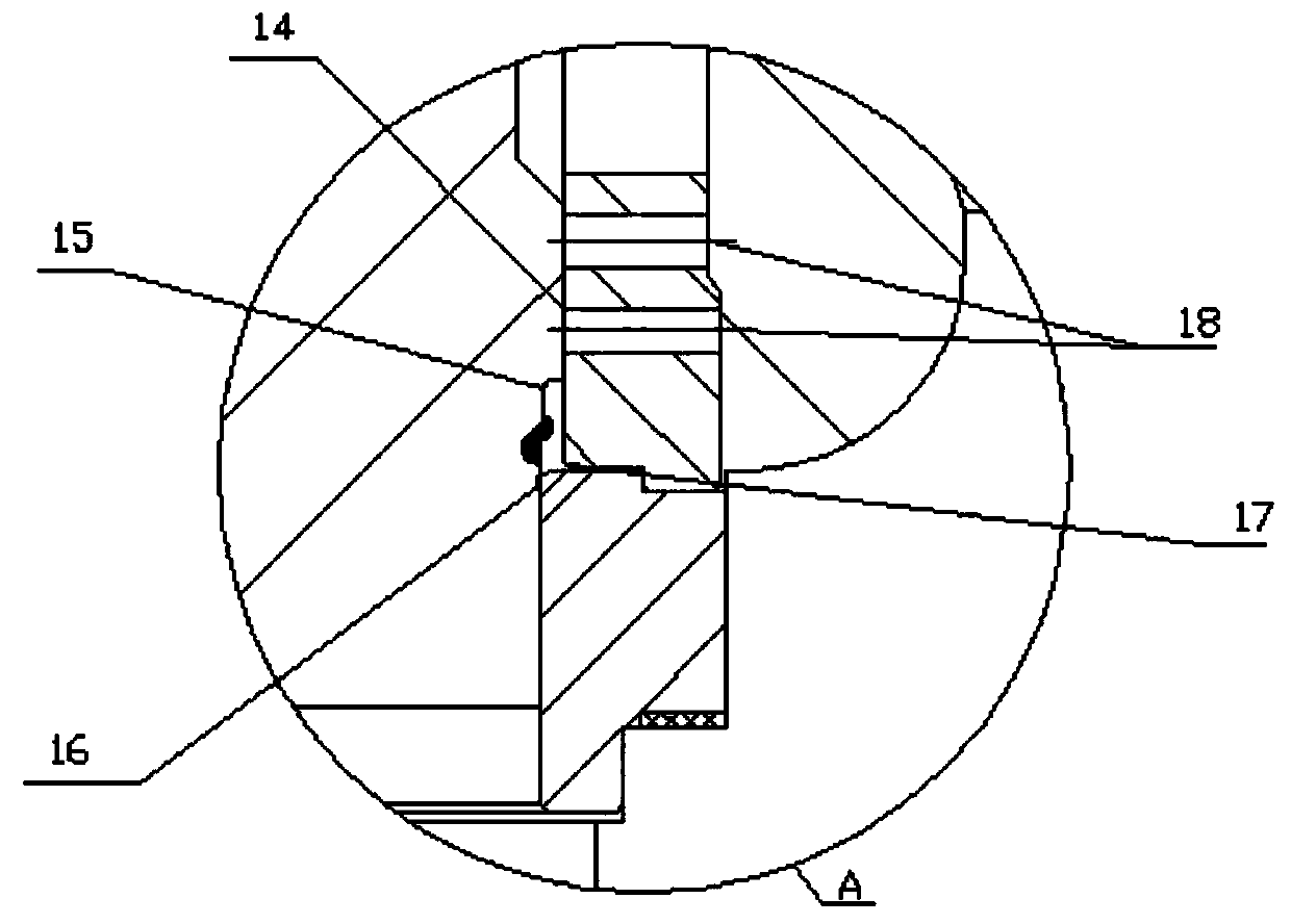
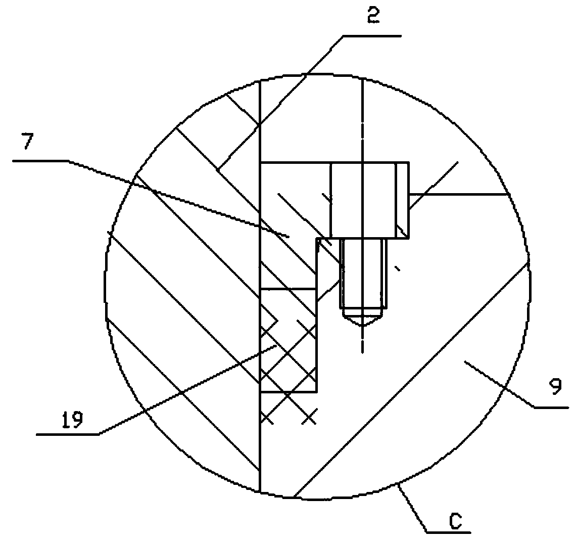
[0026] see Figure 1 to Figure 5 , the present invention provides a technical solution: a new type of high temperature and high pressure regulating valve, including a valve body 3, a valve seat 1, a main valve core 9, a valve cage 2, a valve cover 4, a valve stem 5, a pre-opening valve seat 12, a pre-opening valve seat 12, a Opening valve core 10, disc spring 11, valve core auxiliary seal 8, valve cover seal 6, gland 7, guide centering structure 16, valve seat...


PUM


Abstract

The invention discloses a novel high-temperature high-pressure regulation valve, which comprises a valve body, a valve seat, a main valve element, a valve cage, a valve cover, a valve rod, a pre-opened valve seat, a pre-opened valve element, a disc spring, a valve element auxiliary seal, a valve cover seal, a pressing cover, an oriented centring structure, a valve seat seal and a pre-opened valve.The novel high-temperature high-pressure regulation valve is characterized in that a slope between the main valve element and the valve seat is a big-taper sealing surface, and the valve element auxiliary seal is arranged between the main valve element and the valve cage. By use of the detachable valve seat, the problem that the valve seat and the valve body can not be disassembled sine the valveseat and the valve body are tightly combined due to oxidization after high-temperature high-pressure work can be solved, a sealing surface can be conveniently and easily subjected to resurfacing welding and grinding when the valve seat is overhauled, and quality can be more easily guaranteed.

Description

technical field [0001] The invention belongs to the technical field of high-temperature and high-pressure steam regulating valves, and in particular relates to a novel high-temperature and high-pressure regulating valve. Background technique [0002] The working condition of the high-pressure bypass regulating valve in the main steam pipeline of a steam turbine in a large thermal power plant is extremely harsh. Structural design, material selection, heat treatment process, machining accuracy, installation and commissioning, maintenance quality and cycle, service life, safety, reliability, etc. all have very strict requirements. There are systematic and high requirements. Since my country began to gradually introduce subcritical, supercritical, and ultra-supercritical units in the 1990s, and the single-unit capacity has ranged from 300MW, 600MW to 1000MW and other large-scale power generation devices, my country has gone through the process of overall introduction and domest...

Claims


Application Information

Patent Timeline
Patent Type & Authority Applications(China)
IPC IPC(8): F16K3/26F16K3/314F16K39/04F16K47/08F16K27/08
CPCF16K3/243F16K3/267F16K3/314F16K27/08F16K39/04F16K47/08
Inventor 董玉泉阳运树
Owner YICHUAN TECH CHENGDU CO LTD
Why Eureka
Try Eureka