Metal removing device and achieving method thereof

A metal removal device and metal technology, which is applied to the metal removal device that removes impurities efficiently, in the field of intelligence and high precision, can solve the problems of large production flow fluctuations, large amount of materials, metal inclusions, etc., and achieve simple and stable structure, Guaranteed detection accuracy and high detection accuracy

Inactive Publication Date: 2017-07-18
DINGHAN TECH XIAMEN
View PDF0 Cites 2 Cited by
  • Summary
  • Abstract
  • Description
  • Claims
  • Application Information

AI Technical Summary

Problems solved by technology

[0002] During the production process, the film is more or less mixed with metal, which affects the quality and practical life of the product; for this reason, there is often a process of picking materials in production, and the existing technology has workers looking for metal after the machine stops until the metal is removed. Resume production only after finding, and automatic detection and picking of machine tools
[0003] In the actual production process, manual selection is difficult and intensive, and the elimination effect cannot be guaranteed. However, manual selection is hysteresis, and manual selection is intermittent, so it will cause large fluctuations in production flow; in existing machine tools, automatic There are still some problems in the detection. The metal detector cannot detect metal objects completely and effectively, especially when the belt conveyor frequently starts and stops and two or more metal objects appear in succession. The program will automatically clear the signals of the first few metal objects and use the last one The signal of the metal object shall prevail, and the first few metal objects cannot be removed, so it is necessary to pick the raw materials containing metal. The amount of material is large, and the labor intensity of picking metal is relatively high.

Method used


Image

  • Metal removing device and achieving method thereof
  • Metal removing device and achieving method thereof
  • Metal removing device and achieving method thereof

Examples


Embodiment Construction

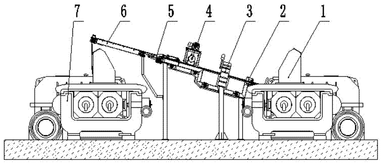
[0021] Such as figure 1 As shown, the present invention is a kind of metal rejecting device, and it comprises back and front track open mill 1, back conveying section 2, metal detection section 3, rotary cutter mechanism 4, impurity rejecting mechanism 5, front conveying 6 and back track opening Refining machine7.

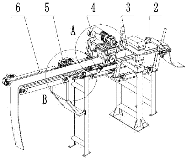
[0022] refer to figure 2 , showing the structural schematic diagram of the front conveying section 6 and the rear conveying section 2 of the present invention, the metal detection section 3, the rotary cutter mechanism 4, and the impurity removing mechanism 5 are sequentially installed on the rear conveying section 2 obliquely in a line, and the front conveying section 6 is placed at the forefront of the metal removal device.

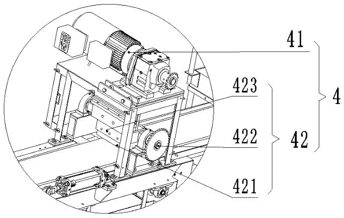
[0023] refer to image 3 , shows a schematic structural view of the rotary cutter mechanism 4 of the present invention, the rotary cutter mechanism 4 includes a motor 41 and a hot knife cutting device 42; the motor 41 is fixed above the ...


PUM


Abstract

The invention discloses a metal removing device, which comprises a front mill, a rear conveying section, a metal detection section, a rotary cutter mechanism, an impurity removing mechanism, a front conveying section and a rear mill; a metal detection section, a rotary cutter The knife mechanism and the impurity removal mechanism are installed on the rear conveying section in a straight line, and the front conveying section and the rear conveying section are arranged obliquely upward, and the rear conveying section conveys the film extruded by the front mill uphill. The metal detection section detects whether the material contains metal, and the rotary cutter mechanism cuts off the material containing metal, and the impurity removal mechanism discharges the cut material and sends the main film to the front conveying section, and the front conveying section conveys the removed film to the rear Road to open the refining machine. The metal removing device disclosed by the invention is simple in structure, stable and efficient, can realize intelligent, high-precision, and high-efficiency removal of impurities on materials, protect the service life of the roller of the mill and the screw of the extruder, and greatly improve the refining efficiency. Glue quality.

Description

technical field [0001] The invention relates to the field of film metal removal devices, in particular to an intelligent, high-precision and high-efficiency metal removal device for removing impurities and a realization method thereof. Background technique [0002] During the production process, the film is more or less mixed with metal, which affects the quality and practical life of the product; for this reason, there is often a process of picking materials in production, and the existing technology has workers looking for metal after the machine stops until the metal is removed. Resume production after finding it, and automatic detection and picking of machine tools. [0003] In the actual production process, manual selection is difficult and intensive, and the elimination effect cannot be guaranteed. However, manual selection is hysteresis, and manual selection is intermittent, so it will cause large fluctuations in production flow; in existing machine tools, automatic ...

Claims


Application Information

Patent Timeline
Patent Type & Authority Applications(China)
IPC IPC(8): B29B7/30B29B7/58B29B7/72
CPCB29B7/30B29B7/58B29B7/72B29B7/722
Inventor 沈展王俊彪陈雅娟郑月苹李莉吴艳瑕
Owner DINGHAN TECH XIAMEN
Why Eureka
Try Eureka