
Elevator

An elevator and traveling cable technology, which is applied to elevators in buildings, lifting equipment in mines, transportation and packaging, etc., can solve the problem of poor elevator comfort, large force on guide shoes, and deflection of reverse sheave force. and other problems to achieve the effect of solving the worsening of elevator comfort and ensuring comfort

Pending Publication Date: 2017-07-18
SJEC CORP
View PDF5 Cites 1 Cited by
  • Summary
  • Abstract
  • Description
  • Claims
  • Application Information

AI Technical Summary

Problems solved by technology

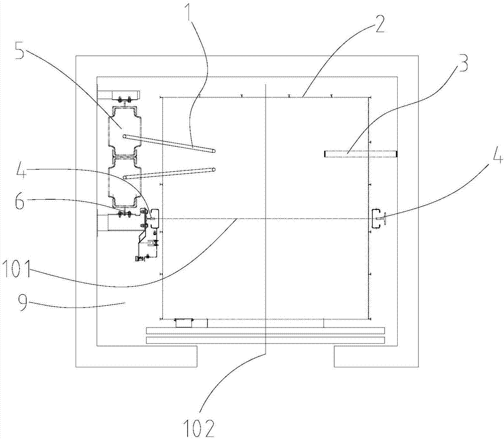
However, when the elevator starts to run, such as when the elevator goes up, the weight suspended by the steel wire rope compensating device 1 and the accompanying cable 3 is getting larger and larger, but there is no corresponding weight to balance it, causing the car assembly 2 to deflect backward, and the guide shoes are stressed. Larger, even the reverse rope pulley will be deflected
Especially for elevators with large tonnage and relatively high hoisting height, the more serious the deflection, the long-term operation will lead to poor comfort of the elevator

Method used


Image

  • Elevator
  • Elevator

Examples


Embodiment Construction

[0020] The present invention can be further clearly understood through the specific examples of the present invention given below, but they are not intended to limit the present invention. Parts not described in detail in the specific embodiments are obtained by using existing technologies, known technical means and industry standards.

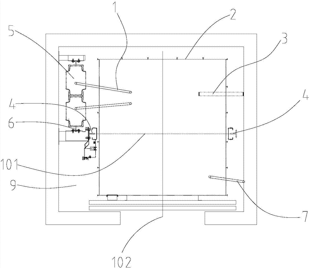
[0021] Such as figure 2 As shown, the present embodiment is an elevator, comprising a state compensation device 7, a counterweight 5, a wire rope compensation device 1, an accompanying cable 3 and a car assembly 2 that is movably installed on the car guide rail 4 in the hoistway 9, and the car assembly 2 Including the car and the car frame (not shown in the figure), the counterweight 5 is movably installed on the counterweight guide rail 6 in the hoistway 9, the wire rope compensation device 1 and the accompanying cable 3 are installed on one side of the plane where the car guide rail 4 is located , the dynamic compensation device 7 is insta...


PUM


Abstract

The invention discloses an elevator. The elevator comprises a dynamic compensating device, a steel wire rope compensating device, a traveling cable, a counterweight which is movably installed on a counterweight guide rail inside a hoistway, and a lift car assembly which is movably installed on a lift car guide rail inside the hoistway. The lift car assembly comprises a lift car and a car frame. The steel wire rope compensating device and the travelling cable are installed at one side of the plane where the lift car guide rail is located, and the dynamic compensating device is installed at the other side of the plane where the lift car guide rail is located. The dynamic compensating device comprises a first end and a second end in the length direction of the dynamic compensating device. The first end is fixedly connected to the lift car assembly, and the second end is fixedly connected into the hoistway. According to the elevator, in the operating process of the lift car, dynamic equilibrium of the two sides of the plane where the guide rail is located can be kept, deflection can be avoided, and the comfort feeling of the elevator cannot be deteriorated after long-term operation.

Description

technical field [0001] The invention relates to the technical field of elevators, in particular to an elevator including a dynamic compensation device. Background technique [0002] The premise of a good elevator running comfort is to ensure that the static and dynamic balance of the elevator is good. The static balance of the car can be adjusted by installing a balance iron, but the dynamic balance is more troublesome, and it is necessary to maintain the balance of the parts (such as wire rope compensation devices, accompanying cables, etc.) that change in mass during the operation of the elevator. [0003] Such as figure 1 In the traditional layout structure disclosed in the prior art shown, due to the overall layout of the elevator, the wire rope compensating device 1 and the accompanying cable 3 are located on one side of the car guide rail 4 connecting line. At this time, the static balance of the car can be adjusted by the balance iron. However, when the elevator st...

Claims


Application Information

Patent Timeline
Patent Type & Authority Applications(China)
IPC IPC(8): B66B11/02B66B17/12
CPCB66B11/02B66B17/12
Inventor 刘彦崔洪武
Owner SJEC CORP
Learn More