Light touch switch-based on-off circuit

A technology of switching on and off circuits and light touch switches, which is applied in the direction of electronic switches, electrical components, and adjusting electrical variables, etc., to achieve the effect of reducing power consumption and saving hardware costs

Inactive Publication Date: 2017-07-18
SHENZHEN HASWARE TECH DEV CO LTD
View PDF5 Cites 11 Cited by
  • Summary
  • Abstract
  • Description
  • Claims
  • Application Information

AI Technical Summary

Problems solved by technology

[0002] There are mainly two ways to turn on and off the existing electronic products: the first one is a toggle switch, turning the switch to the left (or right) to turn it on, and turning the switch to the right (or left) to turn it off; the second The second is a self-locking swi

Method used


Image

  • Light touch switch-based on-off circuit
  • Light touch switch-based on-off circuit
  • Light touch switch-based on-off circuit

Examples


Example Embodiment

[0024] It should be understood that the specific embodiments described here are only used to explain the present invention, not to limit the present invention.

[0025] In the following description, use of suffixes such as 'module', 'part' or 'unit' for denoting elements is only for facilitating description of the present invention and has no specific meaning by itself. Therefore, "module" and "component" may be used mixedly.

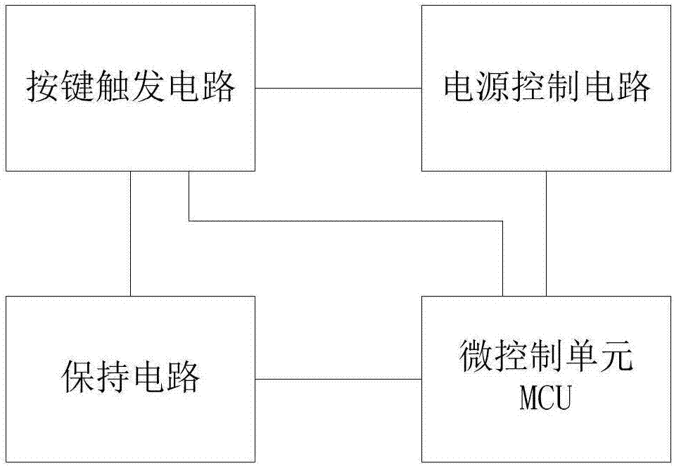
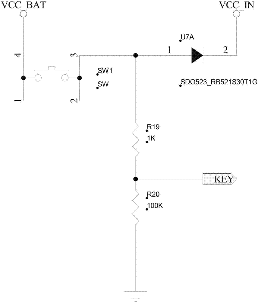
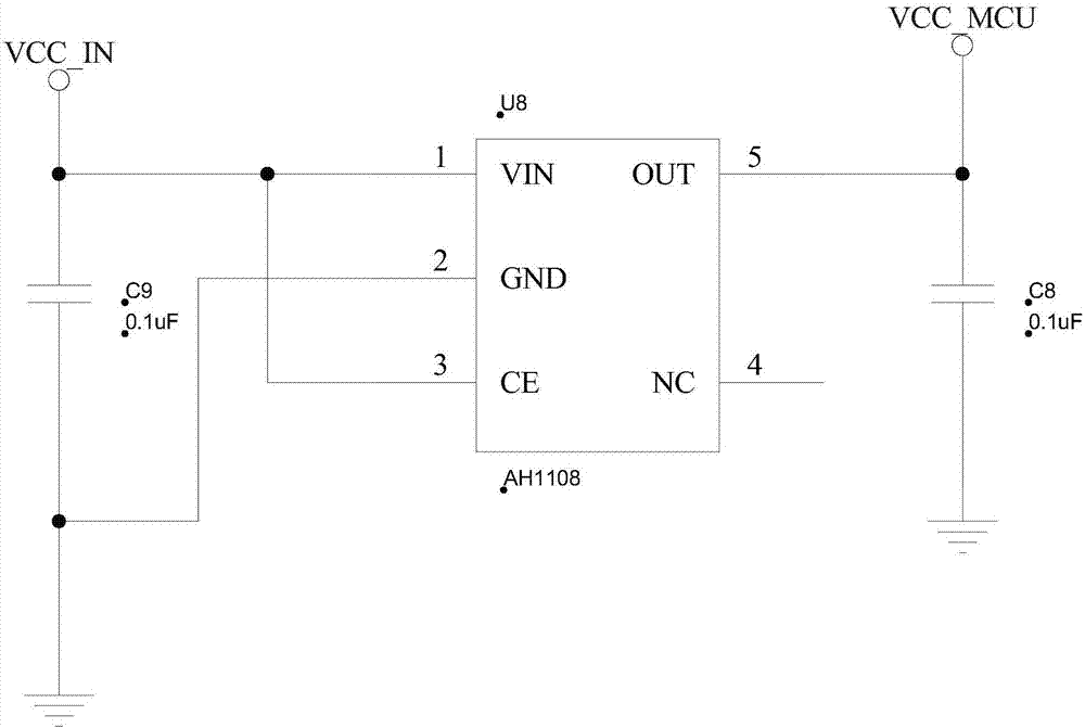
[0026] like figure 1 As shown, in this embodiment, a switch machine circuit based on a tact switch includes: a key trigger circuit, a power supply control circuit, a holding circuit and a micro control unit MCU, the key trigger circuit includes a tact switch, when the When the device corresponding to the tact switch is in the off state, long press the tact switch, and the device is turned on through the power control circuit, the holding circuit and the micro control unit MCU; Press the tact switch to shut down the device, and short press the tact swi...


PUM


Abstract

The invention relates to the technical field of power supply circuits, and discloses a light touch switch-based on-off circuit. The light touch switch based on-off circuit comprises a key triggering circuit, a power control circuit, a holding circuit and an MCU, wherein the key triggering circuit comprises a light touch switch; when a device corresponding to the light touch switch is in an off state, the light touch switch is pressed and held, and then the device can be turned on through the power control circuit, the holding circuit and the MCU; if the device is in an on state, the light touch switch is pressed and held to enable the device to be turned off; the light touch switch can be pressed momentarily to realize button function; the function of the light touch switch can be reused through a software and hardware combining mode; the button function can be realized on the premise that the on-off function is realized. Therefore, the power consumption is decreased, and the hardware cost is reduced.

Description

technical field [0001] The invention relates to the technical field of power supply circuits, in particular to a switch machine circuit based on a tact switch. Background technique [0002] There are mainly two ways to turn on and off the existing electronic products: the first one is a toggle switch, turning the switch to the left (or right) to turn it on, and turning the switch to the right (or left) to turn it off; the second The second is a self-locking switch, press the switch to turn on, press the switch again, the switch bounces up and then shuts down; these two methods are pure hardware control methods, and these two switches can only realize the function of starting and shutting down , can no longer be used as other function keys. Contents of the invention [0003] The main purpose of the present invention is to propose a switch circuit based on a light touch switch, through the combination of software and hardware, the function multiplexing of the light touch sw...

Claims


Application Information

Patent Timeline
IPC IPC(8): G05F1/625H03K17/687H03K17/96
CPCG05F1/625H03K17/687H03K17/96
Inventor 周建波谢成林
Owner SHENZHEN HASWARE TECH DEV CO LTD
Why Eureka
Try Eureka