

Resource distribution method and apparatus
A technology for resource allocation and allocation of resources, applied in the field of resource allocation methods and devices, capable of solving problems such as unproposed solutions
- Summary
- Abstract
- Description
- Claims
- Application Information
AI Technical Summary
Problems solved by technology
Method used
Image

Examples
Embodiment 1
[0132] In this embodiment, it is assumed that the base station allocates resources for the PUSCH of the UE according to the first method, and then sends the resource allocation result to the UE, and further assumes that the preset fixed duration in the first method is 12ms (the case where N is 1), The above assumptions are only for the convenience of illustrating the technical solutions provided by this embodiment, and cannot be used to limit the present invention. On the premise of the foregoing, the first embodiment is specifically divided into three implementation examples for description, each implementation example may refer to each other to understand the present invention, and does not exist in isolation.
[0133] Implementation Example 1
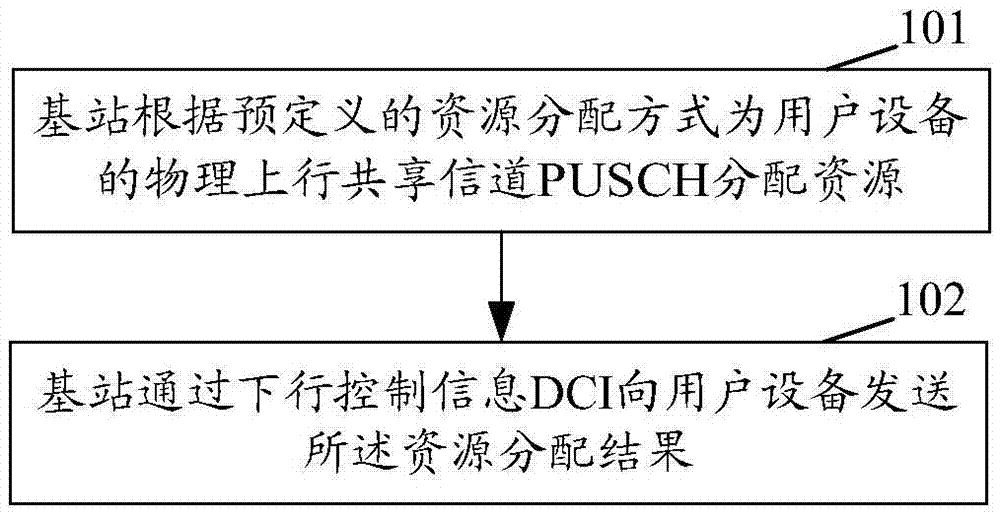
[0134] Since the time domain length corresponding to PUSCH transmission is fixed and is 12ms, the base station allocates resources for PUSCH transmission to the UE, and the base station sends the resource allocation result through DCI;...
Embodiment 2
[0152] In this embodiment, it is assumed that the bit number Y of the information indicating the time domain length corresponding to the PUSCH transmission depends on the minimum value of the maximum number of schedulable resource units and the number of subcarriers, further assuming that the maximum number of schedulable resource units The number is N*M, wherein N=5, M=144, the minimum value of the number of subcarriers is 1, then the maximum value of the time domain length is 60ms ((5*144) / (1*12)=60, where 12 is the number of resource units contained in 1ms), then Y is 6 (2 6 = 64, 6 bits are sufficient to indicate 60ms).
[0153] Implementation Example 1
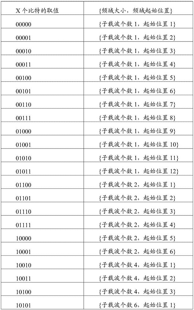
[0154] In addition, in this embodiment, it is assumed that the base station allocates resources for the UE's PUSCH according to the second method, and then sends the resource allocation result to the UE through DCI, wherein X bits are used in the DCI to indicate that the PUSCH Transmit information about the correspondin...
Embodiment 3
[0161]In this embodiment, it is assumed that the number of bits Z included in the information indicating the multiple of the time-domain basic unit corresponding to the PUSCH transmission depends on the maximum number of schedulable resource units, the minimum number of subcarriers, and the time-domain basic unit , further assuming that the maximum number of resource units is 5*144 and the time-domain basic unit is a preset 12ms, then the maximum value of the multiple of the time-domain basic unit is 5 (refer to the calculation method in Embodiment 2), and the time-domain The number of bits Z corresponding to the information of the multiple of the basic unit is 3 (2 3 =8, 3 bits are enough to indicate 5 ways).
[0162] In addition, in this embodiment, it is assumed that the base station allocates resources for the UE's PUSCH according to the second method, and then sends the resource allocation result to the UE through DCI; Information about the starting position and frequenc...
PUM
 Abstract
Description
Claims
Application Information