
a wig stand

A wig and horizontal plate technology, applied in the field of wig brackets, can solve the problems of waste, fixed height, affecting the use effect, etc.

Active Publication Date: 2019-02-12
YIWU PAIDUI CLOTHING CO LTD
View PDF6 Cites 0 Cited by
  • Summary
  • Abstract
  • Description
  • Claims
  • Application Information

AI Technical Summary

Problems solved by technology

People usually place the wig on the bracket when not using the wig. The bracket in the prior art cannot be adjusted because the height is fixed, so when a longer wig is placed, a new bracket can only be purchased, resulting in waste. At the same time, the wig will breed bacteria during long-term use, and cleaning the wig will cause deformation and deterioration of the wig, affecting the use effect

Method used


Image

  • a wig stand
  • a wig stand
  • a wig stand

Examples


Embodiment 1

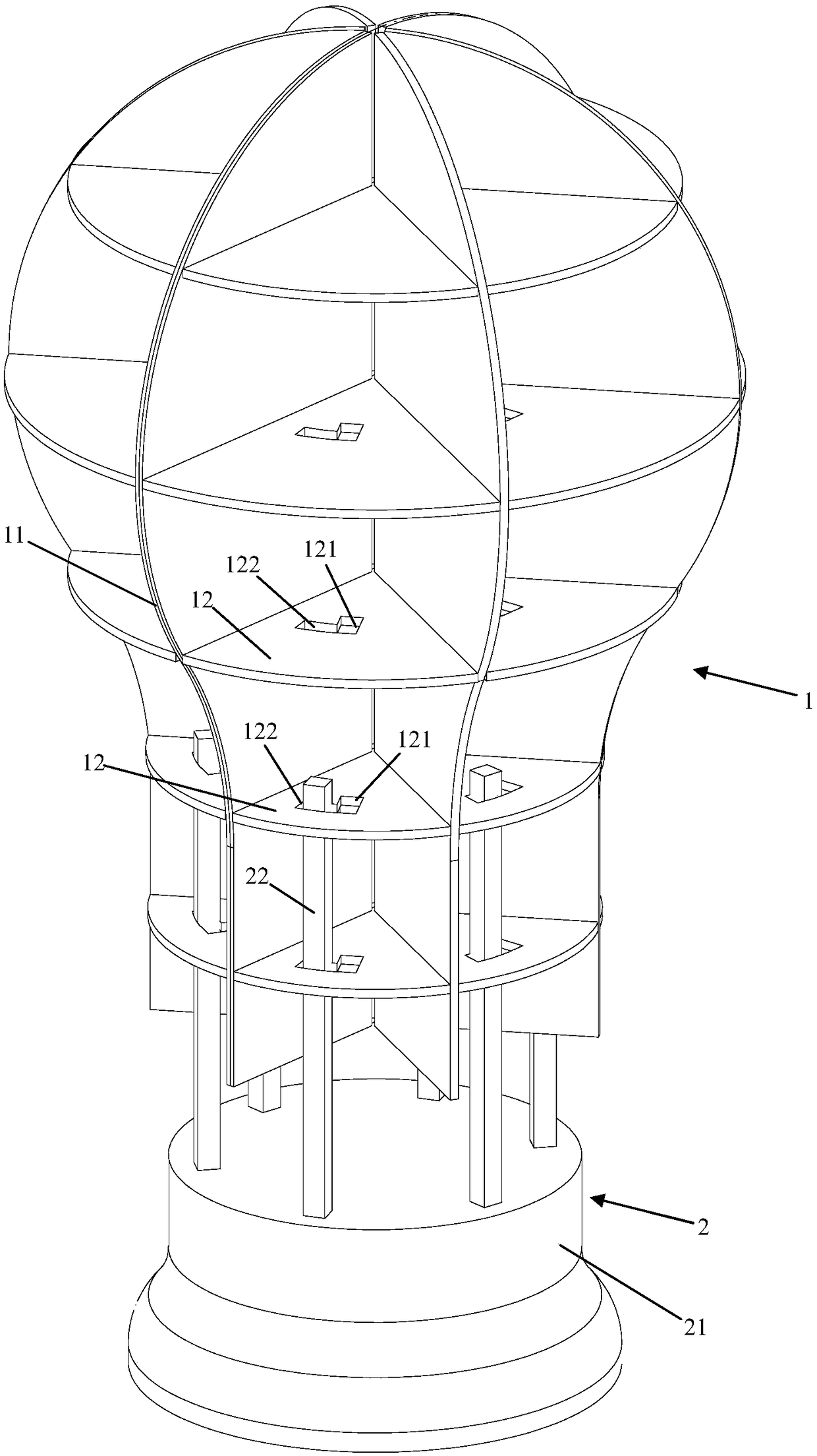
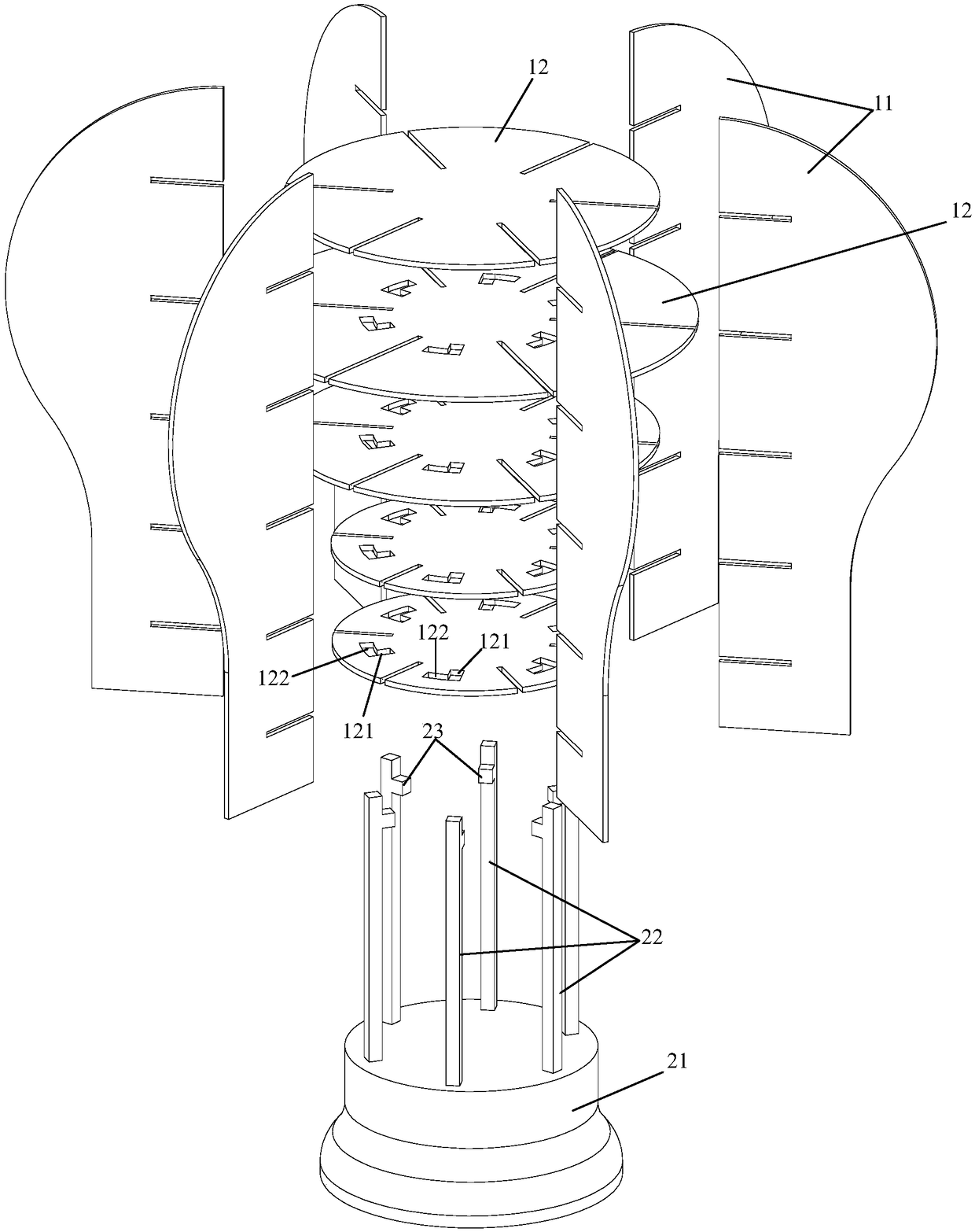
[0013] Such as figure 1 , 2 As shown, the first embodiment provides a wig bracket, including a first part 1 and a second part 2, the first part 1 includes six vertical plates 11 and five circular horizontal plates 12, and the five horizontal plates The plates 12 are coaxially arranged, and the six vertical plates 11 are evenly distributed in the circumferential direction of the five horizontal plates 12, and each of the vertical plates 11 is respectively inserted into the five horizontal plates 12; The second part 2 includes a base 21, six vertical support rods 22 arranged on the upper end surface of the base 21, and the upper inner side of each of the support rods 22 ("inside" and "radially inner" in the present invention) Refers to the radial inner direction of the horizontal plate, "radial outer" means the radial outer side of the horizontal plate) is provided with a support block 23 protruding from the side wall of the support rod 22; in each of the horizontal plates 12 ...

Embodiment 2

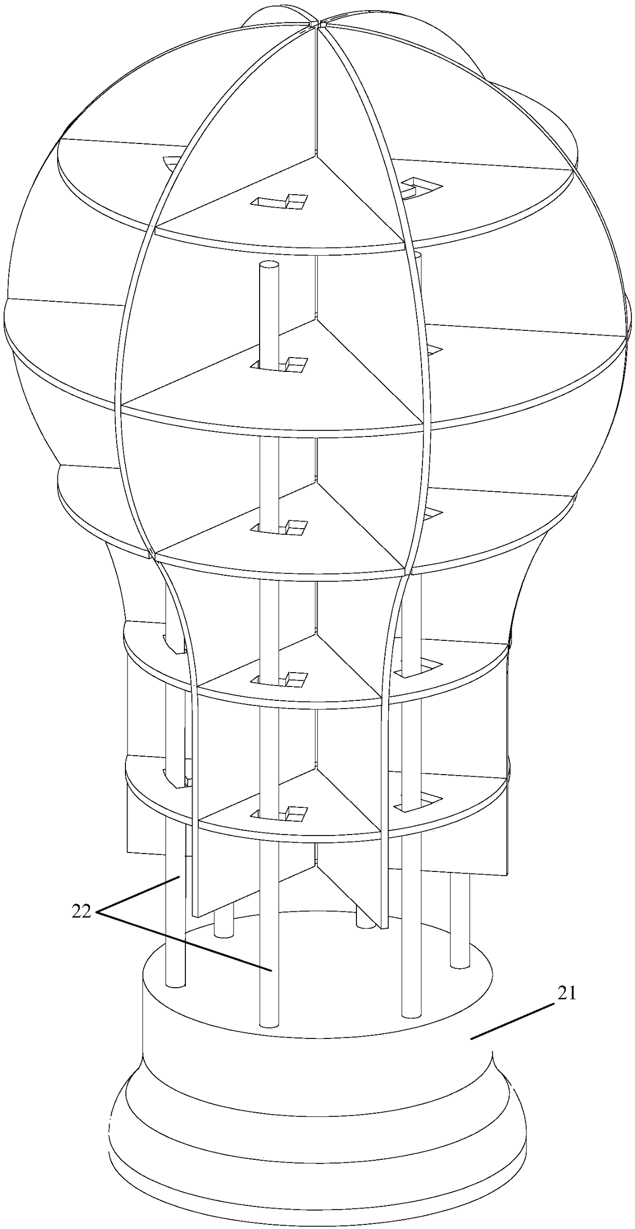
[0018] As shown in the figure, the difference between the second embodiment and the first embodiment is that the support rod 22 is a cylinder made of transparent resin, and an ultraviolet lamp (not shown in the figure) is vertically arranged in the cylinder. out).

[0019] Through the above structure, when the wig is placed on the bracket, the ultraviolet lamp can be turned on to sterilize the wig, so as to ensure that the wig is clean and sterile, healthy and safe; the support rod can not only adjust the height, but also It is also possible to place an ultraviolet lamp to sterilize and disinfect the wig from the inside to the outside at close range, and there will be no dead angle for disinfection inside the wig.


PUM


Abstract

The invention discloses a wig bracket which comprises a first part and a second part. The first part comprises six vertical plates and five round horizontal plates, wherein the five horizontal plates are disposed with the same axis; the six vertical plates are uniformly distributed on the circumference direction of the five horizontal plates; and each vertical plate is in insertion connection to the five horizontal plates respectively. The second part comprises a base and six vertical supporting rods disposed on an upper end face of the base, wherein a supporting block raised from the side wall of the supporting rod is disposed on the inner side of the upper part of each supporting rod; and an insertion hole used for passing of the supporting rod and the supporting block is disposed on each horizontal plate, and insertion grooves used for passing of the supporting rods are formed in circumferential adjacent positions of the insertion holes. By the technical scheme, height of the bracket can be adjusted.

Description

technical field [0001] The invention relates to a wig bracket, which belongs to the technical field of wigs. Background technique [0002] Wigs are hair made by artificial technology and used for decorative accessories. Wigs belong to the hair products industry in the light industry manufacturing industry. The hair products industry is divided into: craft springs, men's hair blocks, women's wigs, teaching heads, chemical fiber hair, etc. Wigs are divided into materials: human hair, chemical fiber, human hair mixed Chemical fiber. Wigs are divided into chemical fiber silk and human hair according to the material. Chemical fiber wigs are made of chemical fibers, which are poor in fidelity, feel itchy after wearing, and are easy to react with the scalp, but they are cheap and have a long-lasting styling effect; wigs made of human hair are made of treated pure human hair. It has high fidelity, is not easy to knot, can be baked, dyed, and permed, and is easy to change hairstyl...

Claims


Application Information

Patent Timeline
Patent Type & Authority Patents(China)
IPC IPC(8): A41G3/00A45D44/14
CPCA41G3/00A45D44/14
Inventor 林新福李志萍
Owner YIWU PAIDUI CLOTHING CO LTD
Learn More