

A metal product processing equipment with self-positioning and automatic output functions
A technology for automatic output and metal products, applied in metal processing equipment, metal sawing equipment, manufacturing tools, etc., can solve the problems of low automation, labor-intensive iron rods, troublesome positioning, etc., achieve high efficiency, labor saving, and high work efficiency , The effect of convenient positioning
- Summary
- Abstract
- Description
- Claims
- Application Information
AI Technical Summary
Problems solved by technology
Method used
Image

Examples
Embodiment 1
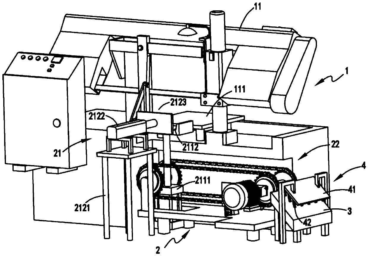
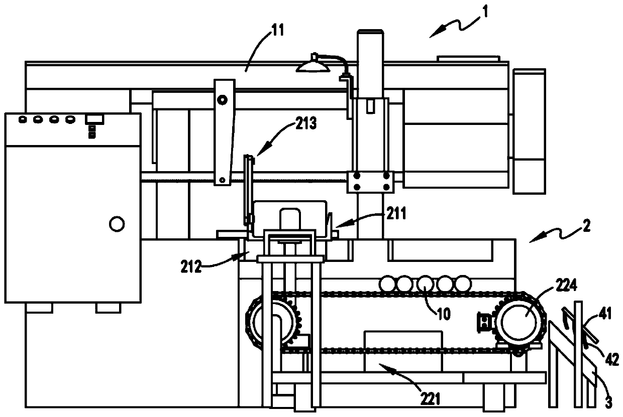
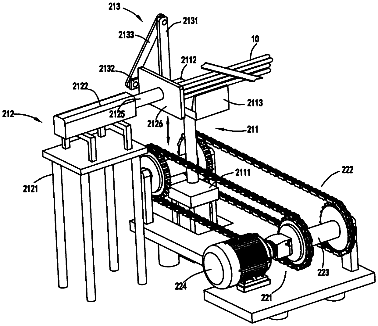
[0034] figure 1 It is a structural schematic diagram of a sawing machine with automatic positioning and output functions, figure 2 It is a schematic diagram of the front view of the sawing machine with automatic positioning and output function, image 3 It is a schematic diagram of the structure when the output part completes the positioning of the iron rod, Figure 4 It is a schematic diagram of the structure of the output part of the iron bar when it is exported with the conveying device a and the conveying device b, Figure 5 Schematic diagram of the positioning support mechanism, Image 6 It is a schematic side view of the iron rod when it is on the conveying device a and conveying device b, Figure 7 Schematic diagram of the structure of the buffer device. Such as figure 1 , figure 2 , image 3 , Figure 4 , Figure 5 , Image 6 with Figure 7 As shown, a metal product processing equipment with self-positioning and automatic output functions includes a main p...
Embodiment 2
[0049] Such as figure 1 , figure 2 , image 3 , Figure 4 , Figure 5 , Image 6 with Figure 7 As shown, the parts that are the same as or corresponding to those in the first embodiment are marked with the corresponding reference numerals in the first embodiment. For the sake of simplicity, only the differences from the first embodiment are described below. The difference between the second embodiment and the first embodiment is that a buffer device 4 is arranged on the top of the lead-out plate 3, and the buffer device 4 includes a mounting frame 41 and a mounting bracket 41 along the length and width direction of the inclined surface of the lead-out plate 3. Several elastic sheets 42 on the frame 41.
[0050] By arranging the buffer device 4 at the rear end of the conveying device a221 and the conveying device b222, when the iron rod 10 slides from the conveying device a221 and the conveying device b222, buffering can be realized under the action of the elastic sheet...
PUM
 Abstract
Description
Claims
Application Information