Check patentability & draft patents in minutes with Patsnap Eureka AI!

Cutting Inserts and Cutting Tools

A cutting insert and cutting tool technology, applied in milling cutting inserts, manufacturing tools, gear teeth manufacturing tools, etc., can solve the problems of increased manufacturing cost, easy reduction of machining position accuracy, and decreased rigidity of working machines, etc. cost effect

Active Publication Date: 2019-12-24
TUNGALOY CORP
View PDF9 Cites 0 Cited by
  • Summary
  • Abstract
  • Description
  • Claims
  • Application Information

AI Technical Summary

Problems solved by technology

However, no matter what method is used to cut the insert mounting part, the number of rotation axes that can be freely controlled as the control axis increases by one, so the accuracy of the machining position tends to decrease.
In addition, the rigidity of the machine tool decreases, cutting conditions are limited, and the manufacturing cost tends to increase.

Method used


Image

  • Cutting Inserts and Cutting Tools
  • Cutting Inserts and Cutting Tools
  • Cutting Inserts and Cutting Tools

Examples


Embodiment Construction

[0036] Hereinafter, embodiments will be described in detail with reference to the drawings. In addition, in the following description, terms such as "upper", "lower", "right", "left", "front", and "rear" are used. However, these are used only to facilitate understanding, and are not intended to limit the present invention.

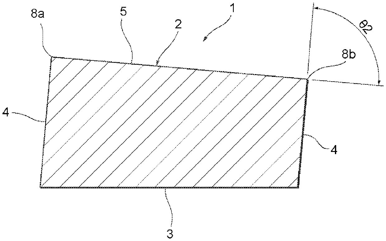
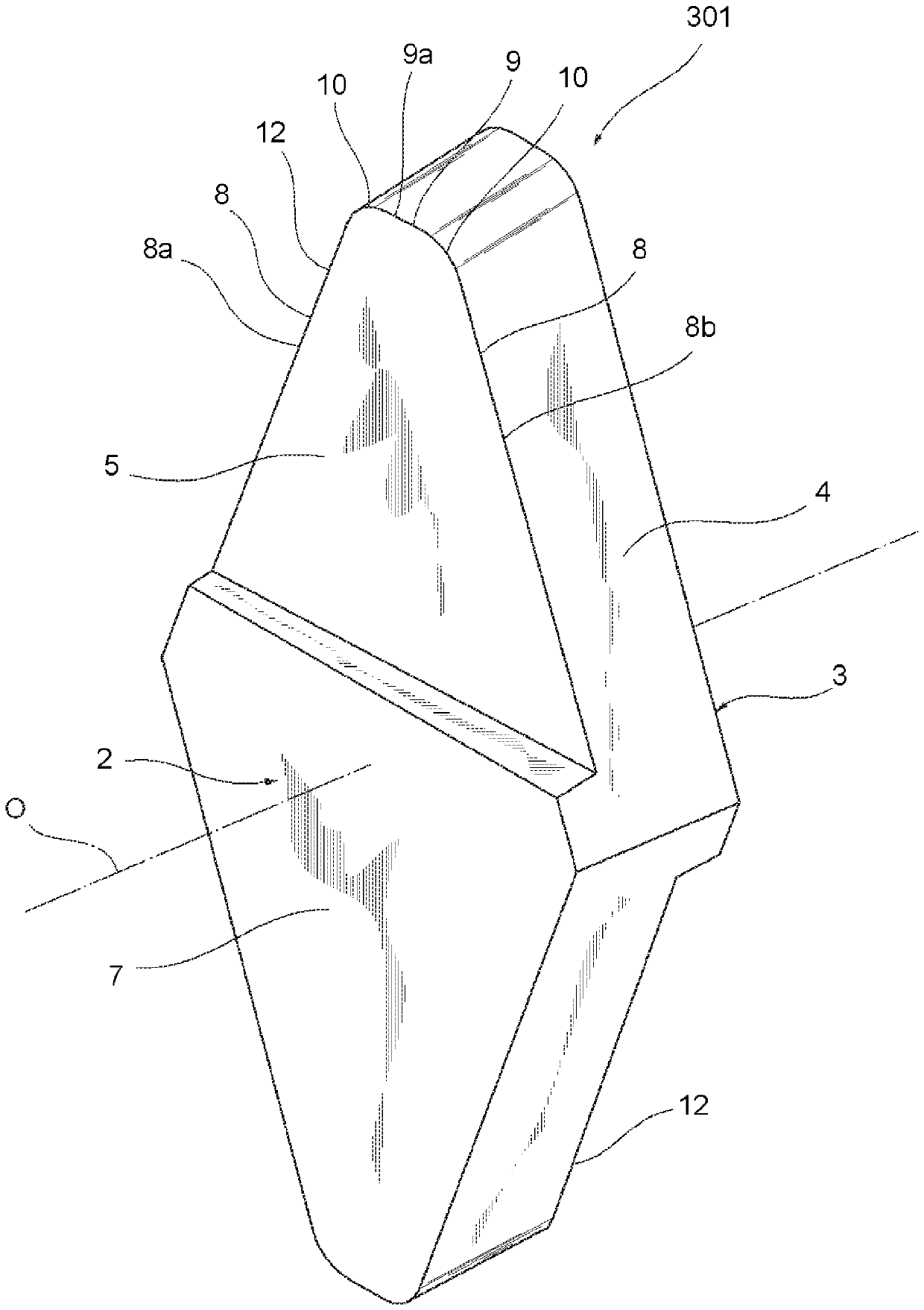
[0037] First, refer to Figure 1 to Figure 8 The cutting insert 1 according to the first embodiment will be described. Such as Figure 1 to Figure 3 As shown, the outer contour of the cutting insert 1 is in the shape of a plate.

[0038] The cutting insert 1 has a first end surface 2 , a second end surface 3 and a peripheral side surface 4 . The first end face 2 has a substantially quadrangular shape. The second end surface 3 is arranged to face the first end surface 2 . The peripheral side surface 4 connects the first end surface 2 and the second end surface 3 . The central axis O is set so as to pass through the substantially central portion of th...


PUM


Abstract

The present invention relates to a cutting insert and a cutting tool. The cutting insert has a first end surface and a second end surface facing each other. The first end surface has at least one top and two edge portions extending to sandwich the top. At least part of the two edge portions are cutting edges. The first end face has a rake face connected to the cutting edge. The rake face is inclined relative to the second end face when viewed in a cross section intersecting the two edge portions and perpendicular to the second end face.

Description

technical field [0001] The present invention relates to a cutting insert and a cutting tool including the cutting insert. Background technique [0002] A hob provided with a plurality of cutting inserts is known as a forming cutting tool, particularly a cutting tool for forming gear teeth or the like. The cutting insert has a shaped cutting edge. In addition, the cutting insert is freely attachable to and detachable from the tool body of the hob. In such an exchangeable hob, when the cutting edge is damaged, the cutting blade can be replaced or the orientation of the cutting blade can be changed so that another cutting edge can be used. Therefore, it is not necessary to replace the entire tool. Since such cutting inserts are economical and can be quickly returned to machining, they are widely used in recent production sites where productivity is strictly required. [0003] Patent Document 1 discloses an example of such a tip replaceable hob. The hob has a plurality of c...

Claims


Application Information

Patent Timeline
Patent Type & Authority Patents(China)
IPC IPC(8): B23F21/16
CPCB23F21/166B23C2200/286B23C5/2273B23C2200/0433B23C2200/081B23C2200/085B23C2270/16B23C5/202B23C2200/0438
Inventor 新城裕二
Owner TUNGALOY CORP
Features
  • R&D
  • Intellectual Property
  • Life Sciences
  • Materials
  • Tech Scout
  • Unparalleled Data Quality
  • Higher Quality Content
  • 60% Fewer Hallucinations
Learn More