Flexible pulling out device for temperature measuring and sampling probe of steel making robot
A sampling probe and robot technology, applied in metal processing, metal processing equipment, manufacturing tools, etc., can solve the problems of robot temperature measurement and sampling probe removal process stiffness, low efficiency of repeated operations, etc., to achieve smooth removal and easy drop recycling , to avoid the stiff effect
- Summary
- Abstract
- Description
- Claims
- Application Information
AI Technical Summary
Problems solved by technology
Method used
Image
Examples
specific Embodiment approach 1
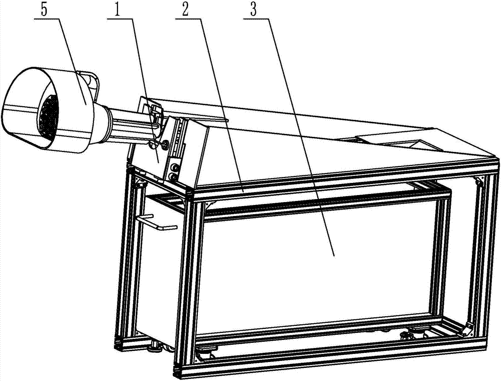
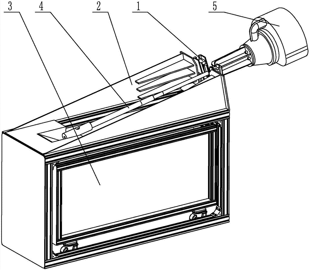
[0016] Specific implementation mode one: combine Figure 1 to Figure 6 Describe this embodiment, a flexible removal device for steelmaking robot temperature measurement and sampling probes described in this embodiment includes a flexible removal assembly 1, an inclined removal frame 2 and a probe recovery trolley 3, the probe recovery trolley 3 is set on an inclined The lower end inside the pull-out frame 2, the flexible pull-out component 1 is arranged on one side of the upper end of the tilt-type pull-out frame 2, the probe 4 is placed on the upper end of the tilt-type pull-out frame 2, the front end of the probe 4 is clamped in the flexible pull-out component 1, the probe 4 is flexibly matched with the flexible extraction component 1 .
[0017] In such a design, when the probe 4 is pulled out, the probe 4 connected with the mechanical arm 5 is slowly put into the flexible pull-out assembly 1, the probe 4 is placed on the upper end of the inclined pull-out frame 2, and the f...
specific Embodiment approach 2
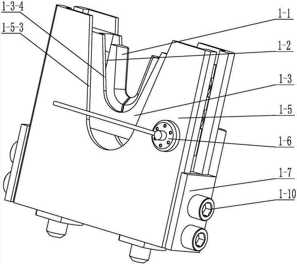
[0018] Specific implementation mode two: combination Figure 1 to Figure 4 Describe this embodiment, the flexible extraction assembly 1 in this embodiment includes a V-shaped extraction block 1-1, a transverse base 1-3, a longitudinal base 1-5, two buffer springs 1-4 and four flexible springs 1 -2, the middle part of the upper end surface of the longitudinal base 1-5 is provided with a rectangular groove 1-5-1, the transverse base 1-3 is arranged in the rectangular groove 1-5-1, and the lower end surface of the transverse base 1-3 Two vertical guide rods 1-3-1 are vertically arranged, and two bottom surface through holes 1-5-2 are arranged on the bottom of the rectangular groove 1-5-1, and each vertical guide rod 1-3-1 Correspondingly inserted in a through hole 1-5-2 on the bottom surface, the outer side of the vertical guide rod 1-3-1 is set with a buffer spring 1-4, and the buffer spring 1-4 is arranged on the lower end surface of the horizontal base 1-3 Between the groove ...
specific Embodiment approach 3
[0021] Specific implementation mode three: combination Figure 1 to Figure 4 To describe this embodiment, a potentiometer 1-6 is provided on the front end surface of the longitudinal base 1-5 in this embodiment. Other compositions and connection methods are the same as those in the second embodiment.
[0022] In such a design, when the probe 4 enters the V-shaped pulling block 1-1 and reaches the predetermined pre-tightening position, the potentiometer 1-6 feeds back a signal, and then the mechanical arm 5 performs the pulling operation, which improves the accuracy of the pulling position and improves efficiency.
PUM
 Abstract
Description
Claims
Application Information
 - R&D
- Intellectual Property
- Life Sciences
- Materials
- Tech Scout
- Unparalleled Data Quality
- Higher Quality Content
- 60% Fewer Hallucinations
Browse by: Latest US Patents, China's latest patents, Technical Efficacy Thesaurus, Application Domain, Technology Topic, Popular Technical Reports.
© 2025 PatSnap. All rights reserved.Legal|Privacy policy|Modern Slavery Act Transparency Statement|Sitemap|About US| Contact US: help@patsnap.com


