Non-slip lifting hook based on gear and rack

A hook and gear technology, applied in the field of anti-slip hooks, can solve the problems of increasing difficulty in replacing or taking out the sling, reducing work efficiency, wasting manpower, etc., and achieves the effects of saving manpower, improving work efficiency, and easy operation

Inactive Publication Date: 2017-07-21
QINZHOU UNIV
View PDF5 Cites 1 Cited by
  • Summary
  • Abstract
  • Description
  • Claims
  • Application Information

AI Technical Summary

Problems solved by technology

But there is following defect in anti-off design like this: because the anti-slip bar is close to the inwall of hook body hook tip, when taking out or replacing the sling, the anti-slip bar needs to be artificially pressed down toward the inner space of the suspension hook body. The sling is heavy and requires two people to operate, which wastes manpower; in addition, because the anti-slip rod occupies the opening area of ​​the hook body, if the size of the sling is large, the opening area between the anti-slip rod and the hook tip of the hook body is small. This increases the difficulty of replacing or taking out the sling and reduces work efficiency

Method used


Image

  • Non-slip lifting hook based on gear and rack
  • Non-slip lifting hook based on gear and rack
  • Non-slip lifting hook based on gear and rack

Examples


Embodiment Construction

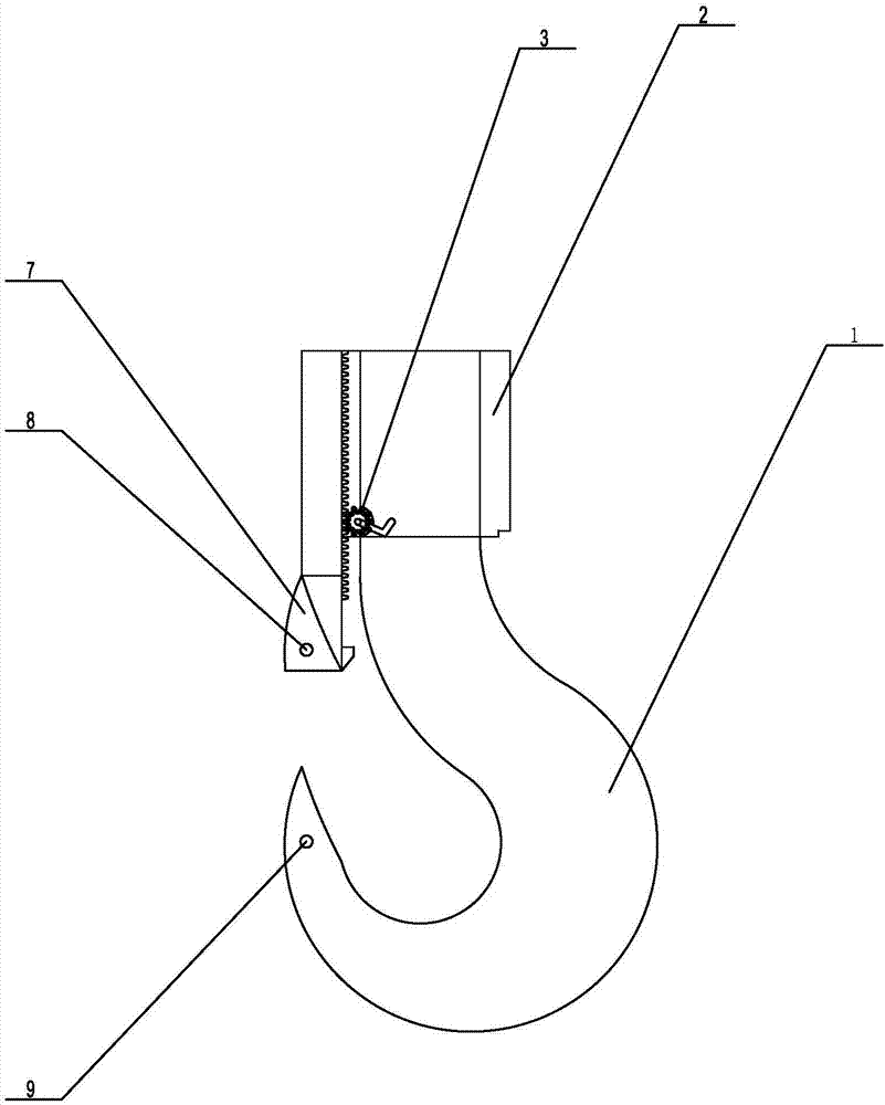
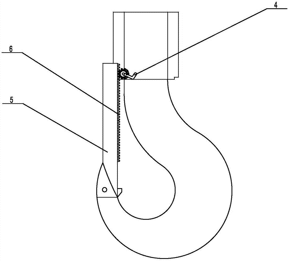
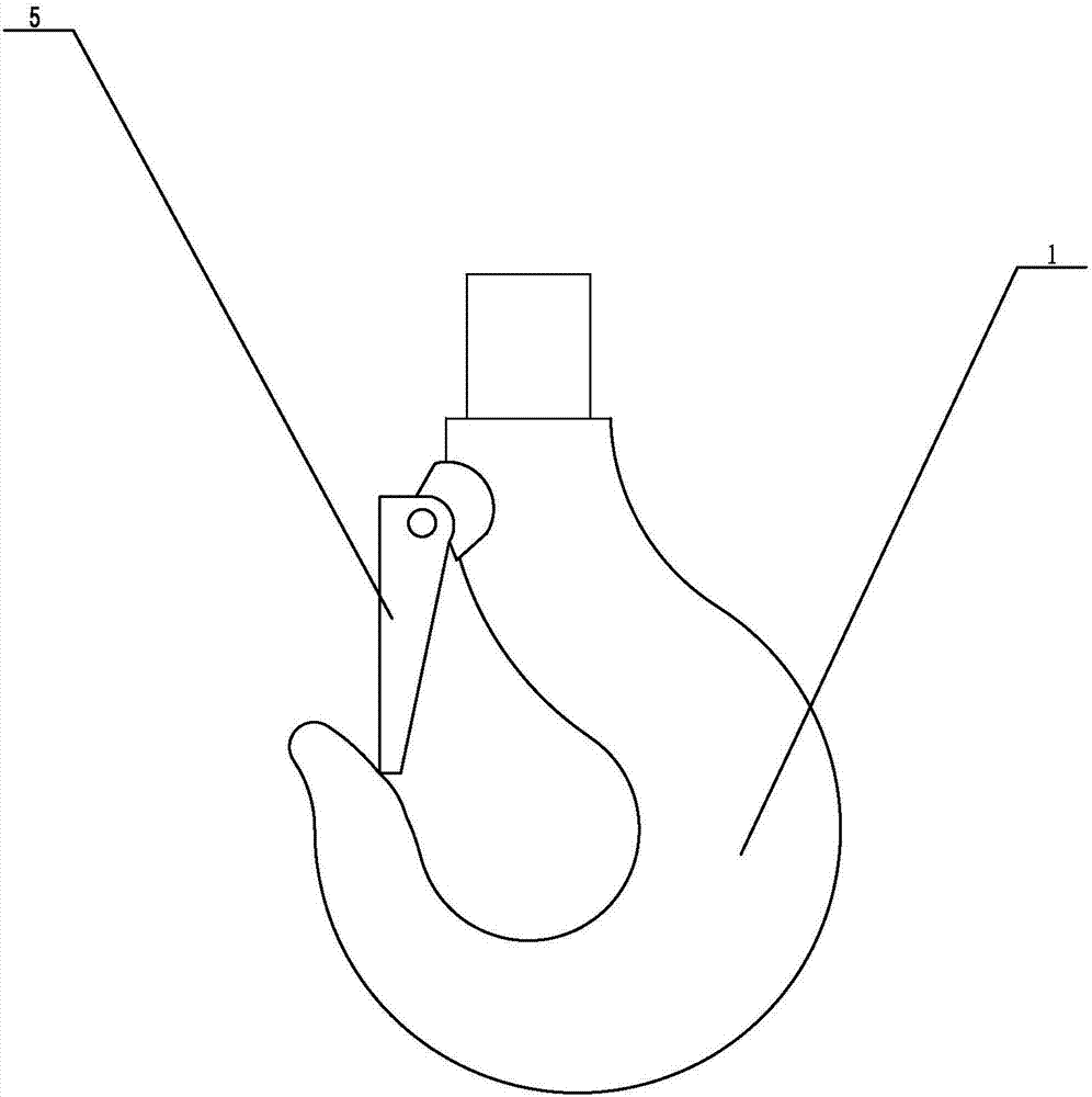
[0018] Such as figure 1 A specific embodiment of the present invention is proposed as shown, the anti-slip hook based on the gear-rack, including the hook body 1, the upper end of the hook body 1 is provided with an anti-slip mounting block 2, and the anti-slip mounting block 2 is fixed A gear 3 is provided. In this embodiment, the gear 3 is located at the bottom of one side of the anti-slip mounting block 2. A hand crank 4 is coaxially installed on the gear 3. Then shaking the hand crank 4 can make the gear 3 rotate. The hook body 1 is movably connected with a vertical anti-slip bar 5 through a connector, and the anti-slip bar 5 can be movably connected to the hook body 1 by buckles or ropes. Moving up and down, the side of the anti-skid bar 5 opposite to the gear 3 is provided with a rack 6 that can mesh with the gear 3, and the bottom end of the anti-skid bar 5 is provided with a hook that can be sleeved on the hook body 1. The hook point cover 7 on the outer surface of t...


PUM


Abstract

The invention discloses a non-slip lifting hook based on a gear and a rack. The non-slip lifting hook comprises a lifting hook body, a non-slip installation block is arranged at the upper end of the lifting hook body, the gear is fixedly arranged on the non-slip installation block, and a crank handle is coaxially installed on the gear; the lifting hook body is movably connected with a vertically-arranged non-slip rod, and the rack capable of being meshed with the gear is arranged on one side of the non-slip rod; a hook tip cover is arranged at the bottom end of the non-slip rod, a hook tip can be sleeved with the hook tip cover, a first locking hole is formed in the hook tip cover, a second locking hole matched with the first locking hole is formed in the hook tip, and the first locking hole and the second locking hole can be locked through a locking piece. The non-slip rod of the non-slip lifting hook is driven to move up and down through the gear and the rack, opening and closing of the lifting hook body are achieved conveniently and rapidly, operation is easy and convenient, manpower is saved, working efficiency is high, unhooking resistance is good, safety performance is high, and the non-slip lifting hook is light, high in strength, long in service life, good in practicability and worthy of being widely popularized.

Description

technical field [0001] The invention relates to a construction machine, in particular to an anti-slip hook based on a gear-rack. Background technique [0002] Cranes, also known as cranes, refer to multi-action hoisting machinery that vertically lifts and horizontally transports heavy objects within a certain range. The working characteristic of the crane is to do intermittent movement, that is, the corresponding mechanisms for taking materials, moving, and unloading in a working cycle are alternately working, and are widely used in industrial production, construction, freight terminals, warehousing and other industries. , mainly used to lift various goods. In addition to the power unit and the steel rope for hoisting, there are also hooks on the crane, and the hook is an important part of the crane. It plays an important role in the whole lifting process and bears all the loads of lifting. Its Safety directly affects the operation of the crane. During use, once the hook i...

Claims


Application Information

Patent Timeline
Patent Type & Authority Applications(China)
IPC IPC(8): B66C1/36
CPCB66C1/36
Inventor 颜晓娟
Owner QINZHOU UNIV
Why Eureka
Try Eureka