
A Method for Suppressing Multiple Reflection False Echoes in Navigation Radar

A multi-reflection, navigation radar technology, applied in radio wave measurement systems, instruments, etc., can solve problems such as excessive suppression intensity, residual false echoes, target loss, etc., and achieve the effect of suppressing multiple reflection false echoes

Active Publication Date: 2019-07-16
HARBIN INST OF TECH
View PDF8 Cites 0 Cited by
  • Summary
  • Abstract
  • Description
  • Claims
  • Application Information

AI Technical Summary

Problems solved by technology

[0003] The purpose of the present invention is to solve the problem that when suppressing the false echoes of multiple reflections of the navigation radar, if the suppression strength is too high, the target will be lost, and if the suppression strength is not enough, the false echoes will remain. Reflection False Echo Suppression Method

Method used


Image

  • A Method for Suppressing Multiple Reflection False Echoes in Navigation Radar
  • A Method for Suppressing Multiple Reflection False Echoes in Navigation Radar
  • A Method for Suppressing Multiple Reflection False Echoes in Navigation Radar

Examples


specific Embodiment approach 1

[0029] Specific implementation mode one: combine Figure 7 , Figure 8 , Figure 9 Describe this embodiment, the specific process of a kind of navigation radar multiple reflection false echo suppression method of this embodiment is:

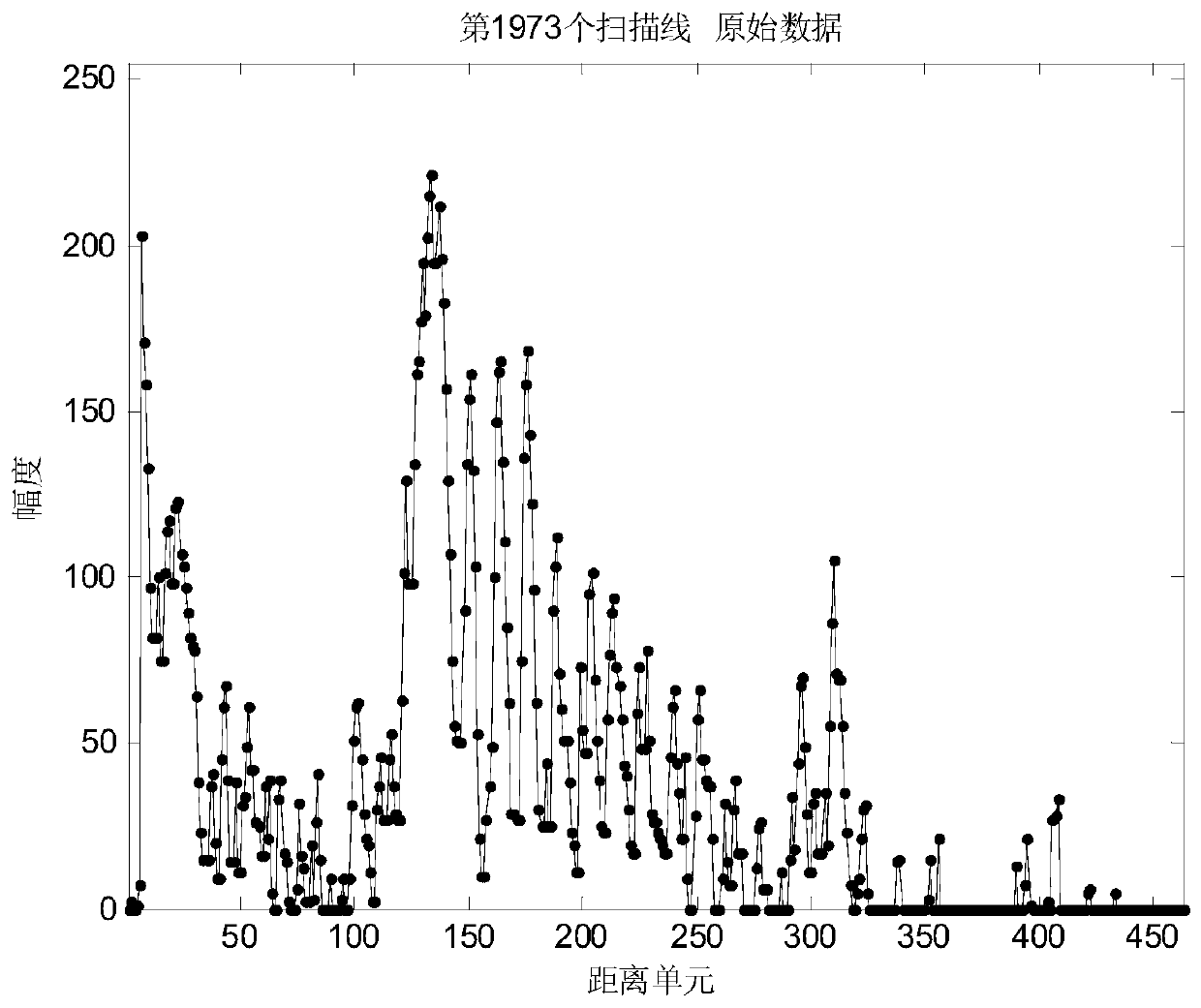
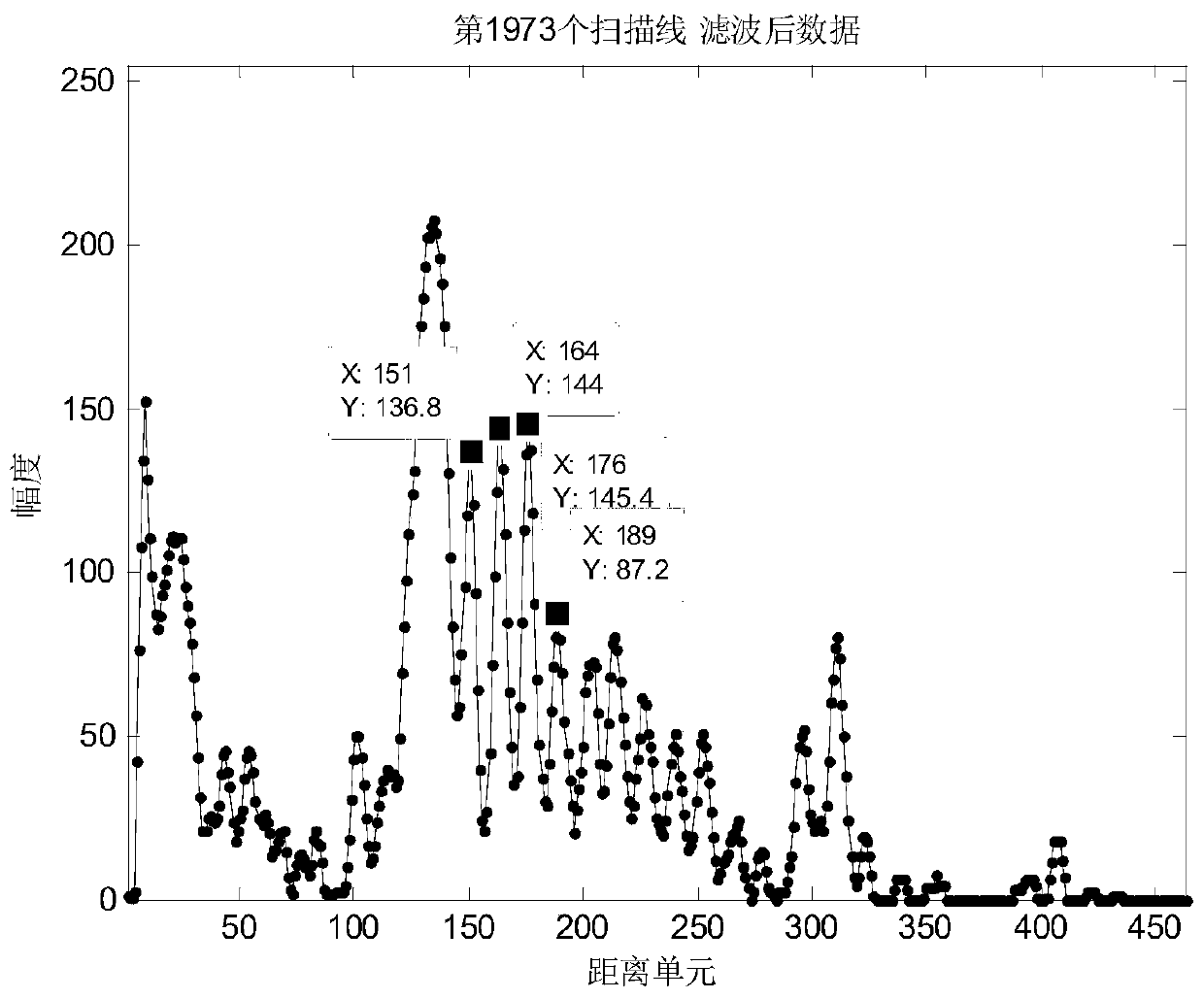
[0030] Step 1. The radar transmits the signal outward, and the receiver receives the echo signal after the radar transmits the signal and irradiates the target, performs mean filtering on the echo signal of the k-th direction along the distance dimension, and obtains the echo after mean filtering data;

[0031] The value of k ranges from 1 to the total number of scan lines output by the navigation radar; the total number of scan lines output by the navigation radar is a positive integer;

[0032] For example: if every 0.25° is a scan line, the total number of scan lines output by the navigation radar is 1440, which is equal to 360° divided by 0.25°;

[0033] Step 2. Extract the features of multiple reflection false echoes from the average fil...

specific Embodiment approach 2

[0041] Specific embodiment 2: The difference between this embodiment and specific embodiment 1 is that in the step 2, the mean value filtered echo data obtained in step 1 is subjected to multiple reflection false echo feature extraction to obtain echoes that meet the conditions Peak position and peak spacing; the specific process is:

[0042] Multiple reflection false echo feature extraction; the specific process is:

[0043] Step 21: Perform peak extraction on the mean-filtered echo data, and perform differential processing. The peak distance obtained after differential processing satisfies: peak distance>T 1 , isometric deviation ≤ T 2 , the number of equidistant ≥ T 3 ;Get the peak position and peak distance of the false echo satisfying the condition;

[0044] The peak extraction process is as follows:

[0045] Generate a matrix of the same size as the echo signal dimension to mark the peak value. The initial value of the matrix is ​​0. When the amplitude values ​​of the ...

specific Embodiment approach 3

[0054] Specific implementation mode three: the difference between this implementation mode and specific implementation mode one or two is that: in the step four, target backfilling is carried out according to the threshold detection result and the echo signal obtained in the step three; the specific process is:

[0055] Extract the target feature X(i,j) from the matrix that stores the threshold detection result in step 3. The target feature X(i,j) includes the target starting distance unit, ending distance unit, maximum amplitude value and target length; i is the stored Target number, the value is a positive integer greater than 1, j is the feature of the target, j=1, 2, 3, 4, corresponding to the target start distance unit, end distance unit, maximum amplitude value and target length;

[0056] Backfilling two adjacent targets needs to satisfy formula (1) and formula (6):

[0057] X(i+1,1)-X(i,2)<=T_range (1)

[0058] T_range=mask_scale-X(i,4)-X(i+1,4) (2)

[0059]

[006...


PUM


Abstract

A method for suppressing multiple reflection false echoes of a navigation radar is disclosed. The invention relates to a method for suppressing multiple reflection false echoes of a navigation radar. The invention aims to solve a problem that target loss is caused if suppression intensity is too large and false echoes remain if the suppression intensity is not enough in suppressing multiple reflection false echoes of a navigation radar at present. The method comprises the steps of (1) obtaining echo data after mean filtering, (2) obtaining an echo peak position and a peak space which satisfy a condition, (3) generating a matrix storage threshold detection result with the same size of an echo signal dimension, (4) carrying out target backfill, (5) obtaining target information, (6) carrying out position information matching on the echo peak position and the target information, and (7) carrying out multiple times of reflection false echo judgment on a successfully matched target, and eliminating a false echo if the false echo exists, otherwise, maintaining the corresponding position value of the target in the matrix. The method is used for the field of radar signal processing.

Description

technical field [0001] The invention relates to a method for suppressing false echoes of multiple reflections of a navigation radar. Background technique [0002] The radar waves reflect back and forth between the own ship and the short-distance strong reflector in the front and back, resulting in multiple reflection false echoes. The weakened false echo, its azimuth and true echo suppression, generally occurs when the distance between the own ship and the strong reflector is within about 1nm when the ship is sailing or anchoring in a narrow channel, and when the beam is facing the beam or is close to the beam , In engineering, the gain is often reduced appropriately and suppressed with the sea wave suppression knob. The problem is that if the suppression strength is too high, the target will be lost, and if the suppression strength is not enough, false echoes will remain. Contents of the invention [0003] The purpose of the present invention is to solve the problem tha...

Claims


Application Information

Patent Timeline
Patent Type & Authority Patents(China)
IPC IPC(8): G01S7/36
CPCG01S7/36
Inventor 李杨王静张宁
Owner HARBIN INST OF TECH
Learn More