
Integrated heat radiation structure of localization device

A heat dissipation structure and device technology, which is applied in the cooling/ventilation of substation/switchgear, modification of power electronics, structural parts of electrical equipment, etc., can solve the problem of inconspicuous heat dissipation, single heat dissipation method, poor heat dissipation, etc. Problems, to achieve the effect of obvious heat dissipation, increase the contact area, and ingenious structure

Active Publication Date: 2017-07-21
TIANJIN JINHANG COMP TECH RES INST
View PDF4 Cites 5 Cited by
  • Summary
  • Abstract
  • Description
  • Claims
  • Application Information

AI Technical Summary

Problems solved by technology

[0002] The construction of smart grid has entered the fast lane, and the newly built smart substations have been widely used. At the same time, a large number of traditional substations are also facing the task of transforming into smart substations. During the transformation of traditional substations, some problems have gradually been exposed. While reducing the size of the in-situ protection device, there is a problem of poor heat dissipation. How to solve the heat dissipation problem is an urgent problem to be solved at present.
However, the integrated heat dissipation structure of the existing in-situ device has a single heat dissipation method, and the heat dissipation effect is not obvious

Method used


Image

  • Integrated heat radiation structure of localization device
  • Integrated heat radiation structure of localization device
  • Integrated heat radiation structure of localization device

Examples


Embodiment Construction

[0015] The following will clearly and completely describe the technical solutions in the embodiments of the present invention with reference to the accompanying drawings in the embodiments of the present invention. Obviously, the described embodiments are only some, not all, embodiments of the present invention.

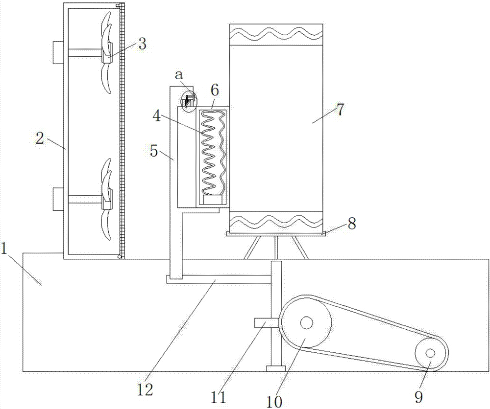
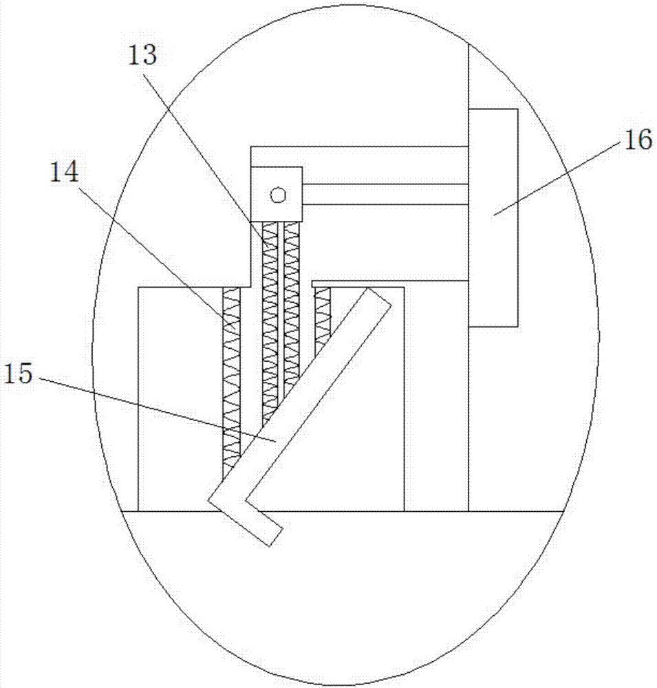
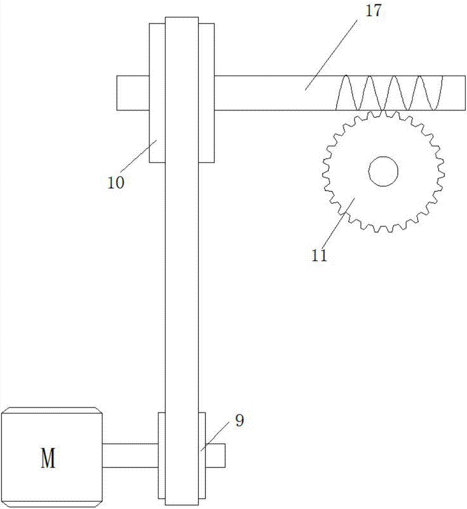
[0016] refer to Figure 1-3 , an integrated heat dissipation structure of an in-situ device, including a base 1, the lower surface of the base 1 is provided with anti-skid lines, the base 1 is coated with a polymer composite film, the base 1 is made of 304 stainless steel, and the base 1 is provided with There is a bellows 2 and a fixed frame 8, the bellows 2 is provided with a box door, and the box door is connected to the bellows 2 in rotation, the bellows 2 is provided with two cooling fans 3 through two first rotating shafts, and each first rotating shaft runs through The bellows 2 is also connected with the first driving motor arranged on the bellows 2, a body 7...


PUM


Abstract

The invention discloses an integrated heat radiation structure of a localization device. The integrated heat radiation structure comprises a base which is provided with an air box and a fixing frame. Two heat radiation fans are arranged on the air box through two first rotating shafts. A machine body is arranged on the fixing frame. Two wavy ventilating ports are symmetrically arranged on the machine body. An annular inserting slot is arranged on the base. An installing frame is inserted in the annular inserting slot. A first connecting rod is fixedly connected at the lower end of the installing frame. One end, which is away from the installing frame, of the first connecting rod is provided with a second rotating shaft. The second rotating shaft is provided with a worm gear. A third rotating shaft and a worm rod are inserted on the base. The third rotating shaft penetrates through the base and is connected with a second driving motor arranged outside the base. A first transmission wheel is arranged on the third rotating shaft. The integrated heat radiation structure is ingenious in structure and convenient to use and performs heat radiation through various heat radiation modes so that the heat radiation effect is more obvious, heat radiation can be more comprehensively performed and the integrated heat radiation structure is worthy of popularization.

Description

technical field [0001] The invention relates to the technical field of heat dissipation devices, in particular to an integrated heat dissipation structure of an in-situ device. Background technique [0002] The construction of smart grid has entered the fast lane, and the newly built smart substations have been widely used. At the same time, a large number of traditional substations are also facing the task of transforming into smart substations. During the transformation of traditional substations, some problems have gradually been exposed. While reducing the size of the in-situ protection device, there is a problem of poor heat dissipation. How to solve the heat dissipation problem is an urgent problem to be solved at present. However, the integrated heat dissipation structure of the existing in-situ device has a single heat dissipation mode, and the heat dissipation effect is not obvious. Contents of the invention [0003] The object of the present invention is to prop...

Claims


Application Information

Patent Timeline
IPC IPC(8): H02B1/56H05K7/20
CPCH02B1/565H05K7/20909H05K7/20927
Inventor 滕维
Owner TIANJIN JINHANG COMP TECH RES INST
Learn More