High-altitude flame-projecting barrier-removing robot

A technology of robots and firearms, applied in the direction of overhead lines/cable equipment, etc., can solve problems that affect the reliable operation of the power grid and the normal power consumption of the society, heavy handling and installation workload, and difficult to guarantee safety, etc., to achieve lightweight, structural Compact and lightening effect

Active Publication Date: 2017-07-21
昆山市工业技术研究院有限责任公司
View PDF5 Cites 3 Cited by
  • Summary
  • Abstract
  • Description
  • Claims
  • Application Information

AI Technical Summary

Problems solved by technology

Obstacles such as balloons and kites hang on the line from time to time. The existing technology usually cuts off the power directly, and manually climbs to the high-voltage line for obstacle removal. Manual obstacle removal consumes a lot of manpower and material resources, and safety is difficult to guarantee.
This method of power outage maintenance or live work is not only dangerous, but also has low work efficiency, which affects the reliable operation of the power grid and the normal power consumption of the society.
There are also some line-clearing robots that usually need to use a crane to place the robot, and the handling and installation workload is relatively large; improper operation or equipment failure is likely to cause personal injury, and there are also major safety hazards

Method used


Image

  • High-altitude flame-projecting barrier-removing robot
  • High-altitude flame-projecting barrier-removing robot
  • High-altitude flame-projecting barrier-removing robot

Examples


Embodiment Construction

[0030] In order to understand the technical content of the present invention more clearly, the following examples are given in detail, the purpose of which is only to better understand the content of the present invention but not to limit the protection scope of the present invention.

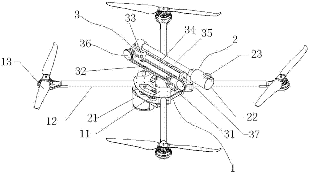
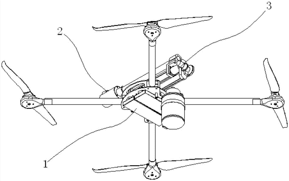
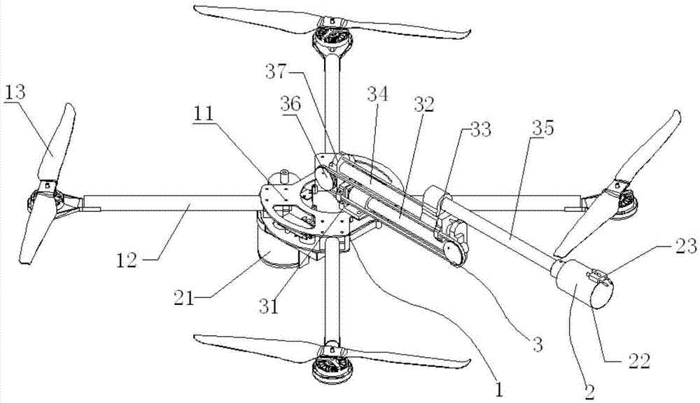
[0031] Such as figure 1 , figure 2 , image 3 and Figure 4 As shown, a high-altitude fire-spraying obstacle removal robot includes a multi-axis aircraft 1 and a fire-spraying system 2, the multi-axis aircraft includes a main frame 11, and the fire-spraying system includes a pressurized fuel tank 21, a nozzle 22 and a high-pressure The igniter 23, the pressurized fuel in the pressurized fuel storage tank can be ignited by the high-pressure igniter after being atomized by the nozzle, and also includes a two-stage telescopic mechanism 3, the two-stage telescopic mechanism includes a first-stage sliding Block 31, primary guide rail 32, secondary slide block 33, secondary guide rail 34, extensi...


PUM


Abstract

The invention discloses a high-altitude flame-projecting barrier-removing robot, including a multi-shaft aircraft two-stage telescoping mechanism and a flame projecting system. The flame projecting system includes a pressurization fuel oil storage tank, a nozzle and a high-pressure igniter, after being atomized through the nozzle, pressurized fuel oil in the pressurization fuel oil storage tank can be ignited by the high-pressure igniter, the two-stage telescoping mechanism includes a first-stage sliding block, a first-stage guide rail, a second-stage sliding block, a second-stage guide rail, an extension rod and a driving device, the first-stage sliding block is slidably arranged on the first-stage guide rail and is fixedly arranged on a main rack of the flame projecting system, and the second-stage sliding block is slidably arranged on the second-stage guide rail; while driving the second-stage sliding block to slide relative to the second-stage guide rail, the driving device drives the first-stage guide rail to slide relative to the first-stage sliding block in the same direction synchronously; and the extension rod is fixedly connected to the second-stage sliding block, and the nozzle and the high-pressure igniter are mounted on the extension rod. The high-altitude flame-projecting barrier-removing robot provided by the invention adopts a remote control flight flame-projecting scheme, and a power supply does not need to be cut off in the barrier removing process, thereby simplifying a barrier removing operation process, lightening the burden of operating personnel, improving the barrier removing efficiency, and ensuring the safety of workers.

Description

technical field [0001] The invention relates to a material retrieving robot for forming and discharging materials from an injection molding machine, in particular to a high-altitude fire-spraying obstacle-clearing robot. Background technique [0002] Power line faults caused by foreign matter connection and discharge on high-voltage lines seriously affect the safe operation of the power grid and the reliable use of electricity in society. Obstacles such as balloons and kites hang on the line from time to time. The existing technology usually cuts off the power directly, and manually climbs to the high-voltage line for obstacle removal. Manual obstacle removal consumes a lot of manpower and material resources, and safety is difficult to guarantee. This method of power failure maintenance or live work is not only dangerous, but also has low work efficiency, which affects the reliable operation of the power grid and the normal power consumption of the society. There are also s...

Claims


Application Information

Patent Timeline
Patent Type & Authority Applications(China)
IPC IPC(8): H02G1/02
CPCH02G1/02
Inventor 谢道鸿樊中文赵广志程胜张建伟
Owner 昆山市工业技术研究院有限责任公司
Why Eureka
Try Eureka