
Weak coverage area detection method and system

A weak coverage, area technology, applied in electrical components, wireless communication and other directions, can solve the problem of difficult promotion, and achieve the effect of improving detection accuracy

Active Publication Date: 2017-07-21
BOCO INTER TELECOM
View PDF3 Cites 19 Cited by
  • Summary
  • Abstract
  • Description
  • Claims
  • Application Information

AI Technical Summary

Problems solved by technology

However, this method requires the UE to record a large amount of data, and this method requires the consent of the UE holder. Therefore, it is difficult to promote the method of using the data reported by the UE to detect weak coverage areas.

Method used


Image

  • Weak coverage area detection method and system
  • Weak coverage area detection method and system
  • Weak coverage area detection method and system

Examples


Embodiment Construction

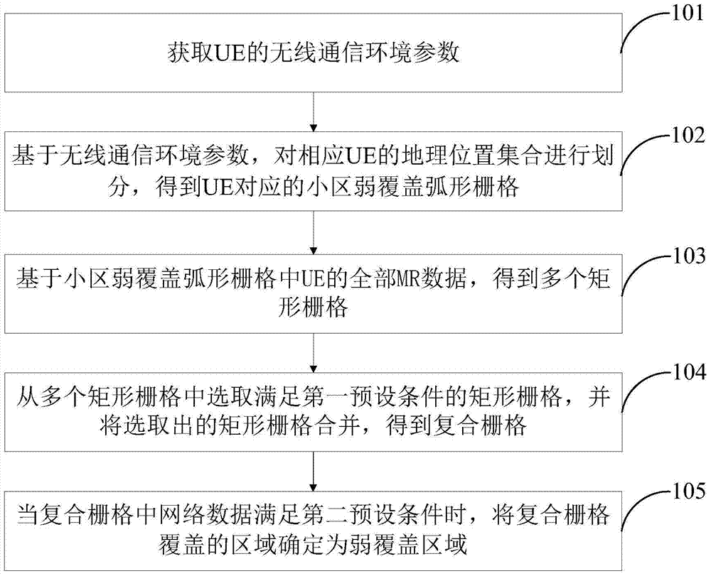
[0067] One of the main ideas of the weak coverage area detection method and system provided by the embodiments of the present invention is: to divide the geographical location set of the user equipment according to the wireless communication environment parameters of the UE to obtain weak coverage areas, and the wireless communication environment of the UE The parameter is the data reported actively by the UE without the consent of the holder, so the difficulty of popularizing the detection method used in the present invention is reduced.

[0068] In order to make the purpose, technical solutions and advantages of the embodiments of the present invention clearer, the technical solutions in the embodiments of the present invention will be clearly and completely described below in conjunction with the drawings in the embodiments of the present invention. Obviously, the described embodiments It is a part of embodiments of the present invention, but not all embodiments. Based on t...


PUM


Abstract

The invention provides a weak coverage area detection method and system. The method comprises the following steps: after acquiring wireless communication environment parameters of UE, dividing a geographical location set of the UE based on the wireless communication environment parameters to obtain cell weak coverage curved grids corresponding to the UE; obtaining multiple rectangular grids based on all MR data of the UE in the cell weak coverage curved grids; selecting the rectangular grids that meet first preset conditions from the multiple rectangular grids, and combining the selected rectangular grids to obtain a composite grid; and when the UE parameters calculated by the composite grid meet second preset conditions, determining an area covered by the composite grid as a weak coverage area. Thereby, the weak coverage area can be detected based on the wireless communication environment parameters of the UE, and the wireless communication environment parameters of the UE are the data actively reported by the UE without the agreement of holders, and thus the promotion difficulty of the detection method provided by the invention can be reduced.

Description

technical field [0001] The invention belongs to the technical field of wireless network optimization, and more specifically relates to a method and system for detecting a weak coverage area. Background technique [0002] A weak coverage area refers to an area where there is a signal but the signal strength cannot meet the network requirements. Under the premise of not setting indoor penetration loss, if the RSRP (Reference Signal Receiving Power, reference signal receiving power) in the area <-100dBm (frequency point 1880-1900MHz) or -98dBm (frequency point 2575-2615MHz) is greater than 5%, then the area is a weak coverage area. The definition of RSRP value is shown in Table 1: [0003] Table 1 RSRP value definition [0004] reported value Measurement data interval distribution (in dBm) RSRP_00 RSRP<-140 RSRP_01 -140≤RSRP<-139 RSRP_02 -139≤RSRP<-138 … … RSRP_95 -46≤RSRP<-45 RSRP_96 -45≤RSRP<-44 ...

Claims


Application Information

Patent Timeline
Patent Type & Authority Applications(China)
IPC IPC(8): H04W24/08H04W24/10
CPCH04W24/08H04W24/10
Inventor 陈明德张东章建功江峰
Owner BOCO INTER TELECOM
Learn More