
Adjustable cyclone separator

The technology of a cyclone separator and a cyclone cylinder is applied in the direction of a cyclone device, a device in which the axial direction of the cyclone can be reversed, etc.

Pending Publication Date: 2017-07-25
SHENTONG TECH GRP CO LTD
View PDF11 Cites 11 Cited by
  • Summary
  • Abstract
  • Description
  • Claims
  • Application Information

AI Technical Summary

Problems solved by technology

[0005] The object of the present invention is to solve the above problems in the prior art, and propose an adjustable cyclone separator, which can adjust the rotation of the exhaust pipe according to the needs, and overcome the exhaust gas impurities caused by the airflow fluctuation More problems, to prevent the disturbance of airflow fluctuations on the internal and external swirl

Method used


Image

  • Adjustable cyclone separator
  • Adjustable cyclone separator
  • Adjustable cyclone separator

Examples


Embodiment 1

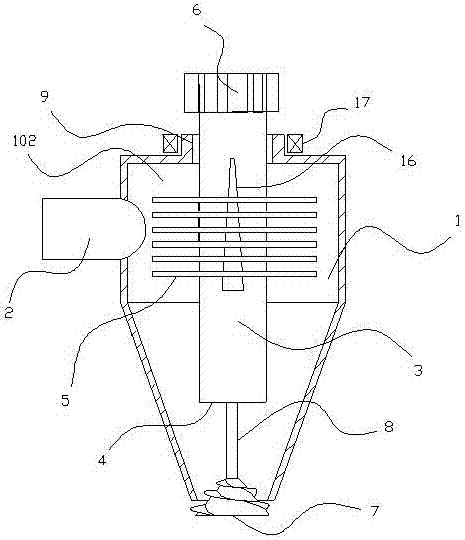
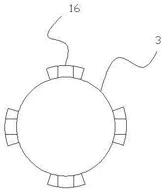
[0024] Such as figure 1 , 2 , As shown in 3 and 4, an adjustable cyclone separator includes a cyclone cylinder body 1, an air inlet pipe 2, an exhaust pipe 3, and a lower port 4 of the cyclone cylinder body composed of a cylindrical chamber and a conical chamber Unicom. The exhaust pipe is rotatably matched with the cyclone cylinder, for example, the two can be matched in a gap. The exhaust pipe is covered with a plurality of discs 5 that can move freely along the exhaust pipe axis. A trapezoidal bump 16 with a small top and a big bottom is arranged in the axial direction, and the disc is provided with a gap 501 that matches the bump. , there is a certain distance between the discs, and the discs can move upwards from the locking point. The discs are soft iron sheets, and an electromagnet 17 for attracting the discs is arranged on the cyclone cylinder. There is a space for storing discs in the upper cyclone cylinder, such as Figure 5 As shown, the discs can be sucked toget...

Embodiment 2

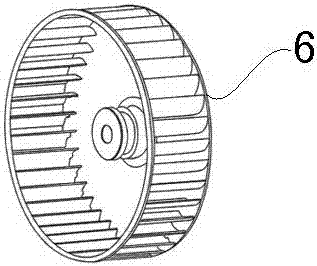
[0028] Such as Figure 6 , 7 As shown, the difference from Embodiment 1 is that in the above-mentioned adjustable cyclone separator, the upper end of the exhaust pipe extends into the transverse air duct 10, and a control exhaust pipe is arranged between the upper end of the exhaust pipe and the transverse air duct. The centrifugal lifting control mechanism for air pipe lifting. The centrifugal lifting control mechanism includes a connecting rod connected between the upper end of the exhaust pipe and the horizontal air guide pipe. The connecting rod is equipped with a flying ball. The structural principle is the same as that of the Watt governor (or called Flying ball governor) is the same, that is, a rotating shaft 11 is set on the transverse air duct, the rotating shaft and the upper end of the exhaust pipe are directly connected with a connecting rod 12, and the hinge connection between the connecting rods is connected with a flying ball 13. When the rotation speed of the ...


PUM


Abstract

The invention provides an adjustable cyclone separator, relates to a cyclone separator, and solves the problem of more discharged gas impurities caused by airflow fluctuation in the prior art. The adjustable cyclone separator comprises a cyclone cylinder formed by communicating a cylinder cavity with a cone cavity, an intake pipe, an exhaust pipe and a cyclone cylinder lower port, and is characterized in that the exhaust pipe is rotationally matched with the cyclone cylinder; spiral blades are arranged on the exhaust pipe; and a centrifugal wind wheel is arranged in an upper end outlet of the exhaust pipe. The adjustable cyclone separator uses the rotation controllable exhaust pipe for reducing the influence on air currents in the cyclone separator by the intake airflow fluctuation, reduces the discharge quantity of impurities along with the air currents, and improves the separation effect.

Description

technical field [0001] The invention relates to a cyclone separator, in particular to an adjustable cyclone separator capable of maintaining stable air flow in the cyclone separator. Background technique [0002] The cyclone separator is a kind of equipment used for the separation of gas-solid system or liquid-solid system. The working principle is to rely on the rotational motion caused by the tangential introduction of the airflow, so that the solid particles or liquid droplets with large inertial centrifugal force are separated from the outer wall. It is a kind of separation equipment widely used in industry. For example, it can be used as an air filter or oil separator in a car. [0003] When the impurity-containing gas enters the cyclone separator at high speed, it will rotate strongly, and the airflow will spiral downward along the cylinder and enter the cyclone cylinder, which is called external swirling flow. The dense liquid droplets or dust particles are thrown t...

Claims


Application Information

Patent Timeline
IPC IPC(8): B04C5/103B04C5/107B04C5/14
CPCB04C5/103B04C5/107B04C5/14
Inventor 方立锋蔡炳芳饶聪超茅锦鑫
Owner SHENTONG TECH GRP CO LTD
Learn More