Supercharge Your Innovation With Domain-Expert AI Agents!

Ultrasonic welding machine

An ultrasonic welding and ultrasonic technology, which is applied in welding equipment, non-electric welding equipment, metal processing equipment, etc., can solve problems that cannot meet modern production, unreasonable structural design, low welding efficiency and low welding quality of briefcases, and achieve improved welding Effects on efficiency and welding quality

Pending Publication Date: 2017-07-25
广东锐军智能设备有限公司
View PDF7 Cites 0 Cited by
  • Summary
  • Abstract
  • Description
  • Claims
  • Application Information

AI Technical Summary

Problems solved by technology

[0002] As one of the commonly used tools for holding paper documents, briefcases are also one of the basic accessories in various office locations. Briefcases are roughly composed of multi-layer plastic films and paper cards installed between the multi-layer plastic films. When actually manufacturing the briefcase, it is necessary to put the paper card between the multi-layer plastic films, and then weld the plastic film and the paper card together; because the welding device used for welding the briefcase in the prior art The structural design of the briefcase is unreasonable, resulting in extremely low welding efficiency and welding quality of the briefcase, which cannot meet the needs of modern production

Method used


Image

  • Ultrasonic welding machine
  • Ultrasonic welding machine
  • Ultrasonic welding machine

Examples


Embodiment Construction

[0029] In order to facilitate the understanding of those skilled in the art, the present invention will be further described below in conjunction with the embodiments and accompanying drawings, and the contents mentioned in the implementation modes are not intended to limit the present invention.

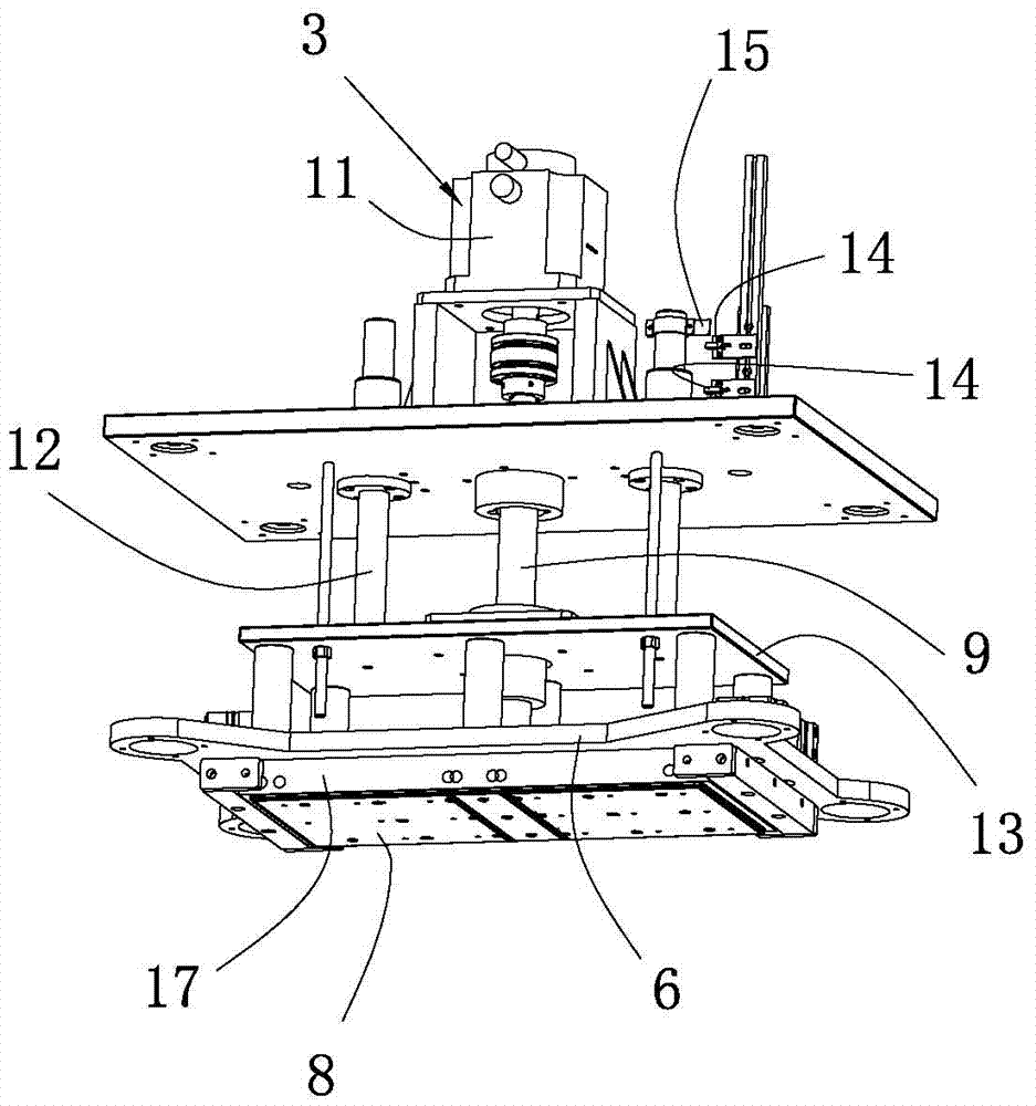
[0030] see Figure 1 to Figure 5 , a kind of ultrasonic welding machine of the present invention comprises a frame body 1, a welding mechanism 2 and a pressing mechanism 3 installed on the frame body 1, and the welding mechanism 2 includes an ultrasonic generator 4 installed on the frame body 1, and The welding head 5 connected to the ultrasonic generator 4; the holding mechanism 3 includes a slide plate 6, a spring 7 and a buffer plate 8, the slide plate 6 and the buffer plate 8 are roughly rectangular flat plates, and the slide plate 6 is slidably connected to the frame body 1. In the embodiment, the buffer plate 8 is located above the welding head 5, the slide plate 6 slides up a...


PUM


Abstract

The invention relates to the technical field of welding devices, and particularly to an ultrasonic welding machine which comprises a frame body, a welding mechanism and a pressing and holding mechanism which are mounted on the frame body, wherein the welding mechanism comprises an ultrasonic generator mounted on the frame body and welding heads connected with the ultrasonic generator; the pressing and holding mechanism comprises a sliding plate, springs and buffer plates; the sliding plate is connected with the frame body in a sliding manner; the buffer plates are arranged in a manner of being parallel with the sliding plate in a spaced manner; the two ends of each of the springs are connected with the sliding plate and the buffer plates respectively; the buffer plates are positioned between the sliding plate and the welding heads; during practical use of the machine, a document folder to be welded is conveyed to the welding heads, the sliding plate drives the buffer plates to move in the direction close to the welding heads, the buffer plates are utilized to enable the document folder to be butted with the welding heads, and the ultrasonic generator is switched on to perform welding on the document folder; during the welding process, the springs are utilized to perform buffering on the document folder clamped by the welding heads and the buffer plates, and therefore the welding efficiency and quality of the document folder is improved.

Description

technical field [0001] The invention relates to the technical field of welding devices, and in particular discloses an ultrasonic welding machine. Background technique [0002] As one of the commonly used tools for holding paper documents, briefcases are also one of the basic accessories in various office locations. Briefcases are roughly composed of multi-layer plastic films and paper cards installed between the multi-layer plastic films. When actually manufacturing the briefcase, it is necessary to put the paper card between the multi-layer plastic films, and then weld the plastic film and the paper card together; The structural design of the briefcase is unreasonable, so that the welding efficiency and welding quality of the briefcase are extremely low, which cannot meet the needs of modern production. Contents of the invention [0003] In order to overcome the shortcomings and deficiencies in the prior art, the object of the present invention is to provide an ultrason...

Claims


Application Information

Patent Timeline
Patent Type & Authority Applications(China)
IPC IPC(8): B23K20/10B23K20/26
CPCB23K20/10B23K20/26
Inventor 朱汉华邹家萌邹卫冯德张虹勋
Owner 广东锐军智能设备有限公司
Features
  • R&D
  • Intellectual Property
  • Life Sciences
  • Materials
  • Tech Scout
  • Unparalleled Data Quality
  • Higher Quality Content
  • 60% Fewer Hallucinations
Learn More