
Winding die for molding interior grid stiffened cylindrical shell structure part and using step

A technology for cylindrical shells and parts, applied in applications, household appliances, household components, etc., can solve the problems of poor surface finish, unstable rib size, difficult demoulding, etc., and achieve good product quality consistency and difficult solutions Difficulty in pressurization and demoulding, effects of high dimensional accuracy and positional accuracy

Inactive Publication Date: 2017-07-25
HENGSHEN
View PDF2 Cites 11 Cited by
  • Summary
  • Abstract
  • Description
  • Claims
  • Application Information

AI Technical Summary

Problems solved by technology

The grid structure made of unidirectional composite materials can give full play to the advantages of composite materials. The continuous improvement of design and manufacturing technology is expected to reduce manufacturing costs as soon as possible, and has broad development prospects and huge potential; the most common forming grid The mold methods are mainly the following three: one is soft mold molding, the USAF Phillips Laboratory (USAF Phillips Laboratory) is in a leading position in technology, and is used to produce solar panels, fairings and missile adapters, but the soft mold The forming method also has its disadvantages. The surface finish of the product is poor, and the size of the ribs is unstable. After the product is cured, the soft mold needs to be split, and the cost is high. At the same time, it will be difficult to demould the structure with a relatively large height / width of the ribs; One method of grid formation is a rigid foam grooved mold solution

Method used


Image

  • Winding die for molding interior grid stiffened cylindrical shell structure part and using step
  • Winding die for molding interior grid stiffened cylindrical shell structure part and using step
  • Winding die for molding interior grid stiffened cylindrical shell structure part and using step

Examples


Embodiment 1

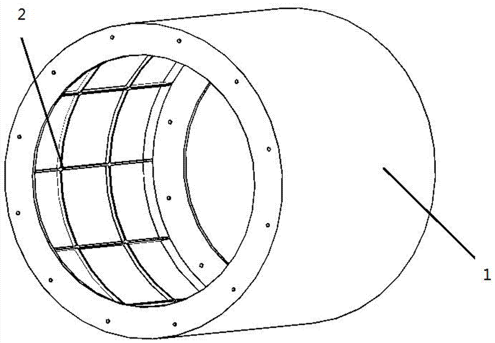
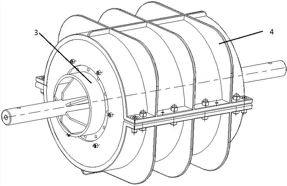
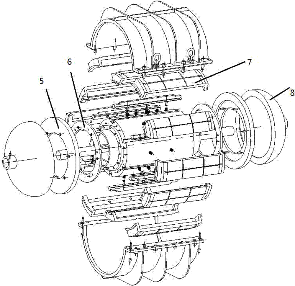
[0025] The present invention is a kind of winding mold for molding inner grid reinforced cylindrical shell structure parts, such as figure 2 , image 3 , including a main body mold 3, a core mold 7, a positioning ring 6, an end frame flange 5, a head 8 and an outer mold 4, the above-mentioned main mold 3 is a steel mold, the core mold 7 is an aluminum mold, and the rest are all steel mold, such as Figure 4 As shown, the mandrel 7 is divided into several petals in the longitudinal direction, such as Figure 4 As shown, a T-shaped block is installed on the split core mold 7, which is assembled with the T-shaped slot 9 provided on the main body mold 3.

[0026] The use process of the mold is as follows: first clean the mold, assemble the mold, then wind the prepreg tape of the reinforcing rib through the winding machine, put the air felt and other vacuum bags for pre-compaction; repeat the above operation until the rib is wound Finished; then pave the skin prepreg, move the ...


PUM


Abstract

The invention relates to a winding die for molding an interior grid stiffened cylindrical shell structure part. The winding die comprises a body die, a core die and an outer die; evenly-arranged T-shaped grooves are formed in the two sides of the body die, the core die and the body die are assembled through T-shaped blocks, the outer die is arranged on the outer side of the core die and used for limiting the appearance of the molded part, end frame flanges facilitating turnup of the molded part are arranged at the two ends of the body die, and sealing heads are arranged on the outer side of the end frame flange. The using steps of the die comprises (1) cleaning and die assembling, (2) reinforcing rib winding, and vacuum bag hitting for pre-compaction; and (3) moving the die to a drying oven for curing, and demolding after curing is carried out. The winding die can be repeatedly used, grid reinforcing ribs of the molded product have the high size accuracy and position accuracy, the product quality consistency is good, and later period assembly of the product is facilitated.

Description

technical field [0001] The invention designs a mold, specifically a winding mold for forming inner mesh reinforced cylindrical shell structural parts and the steps of use. Background technique [0002] With the development of the aerospace industry, especially the continuous improvement of the technological level of aerospace materials, the grid structure of composite materials has been more and more widely used. The grid structure made of unidirectional composite materials can give full play to the advantages of composite materials. The continuous improvement of design and manufacturing technology is expected to reduce manufacturing costs as soon as possible, and has broad development prospects and huge potential; the most common forming grid The mold methods are mainly the following three: one is soft mold molding, the USAF Phillips Laboratory (USAF Phillips Laboratory) is in a leading position in technology, and is used to produce solar panels, fairings and missile adapte...

Claims


Application Information

Patent Timeline
IPC IPC(8): B29C70/30B29C70/34B29C70/54B29L31/00
CPCB29C70/30B29C70/342B29C70/54B29L2031/737
Inventor 杨静文於永红陈明新林志明
Owner HENGSHEN
Learn More