
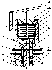
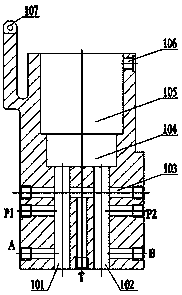
a brake valve

A brake valve and valve body technology, which is applied in the field of hydraulic solenoid valves, can solve problems such as increasing system complexity, and achieve good market application value, reliable operation, and compact structure.

Active Publication Date: 2019-03-29
北京天力益德液压有限公司
View PDF6 Cites 0 Cited by
  • Summary
  • Abstract
  • Description
  • Claims
  • Application Information

AI Technical Summary

Problems solved by technology

The brake valve is more important among the hydraulic control components. The brake valves currently used are generally single-spool brake valves, which require other hydraulic control components to realize oil distribution, which increases the complexity of the system.

Method used


Image

  • a brake valve
  • a brake valve
  • a brake valve

Examples


Embodiment Construction

[0026] In order to facilitate the understanding of the present invention, the present invention will be described in more detail below in conjunction with the accompanying drawings and specific embodiments. Preferred embodiments of the invention are shown in the accompanying drawings. However, the present invention can be implemented in many different forms and is not limited to the embodiments described in this specification. On the contrary, these embodiments are provided to make the understanding of the disclosure of the present invention more thorough and comprehensive.

[0027] It should be noted that when an element is referred to as being “fixed” to another element, it can be directly on the other element or there can also be an intervening element. When an element is referred to as being "connected to" another element, it can be directly connected to the other element or intervening elements may also be present. The terms "vertical", "horizontal", "left", "right" and...


PUM


Abstract

The invention discloses a brake valve. The brake valve comprises a valve body, a left valve core, a right valve core, an end cover and an ejector rod. The valve body is provided with a left valve hole, a right valve hole, a push plate hole, an end cover hole, a left oil inlet hole, a right oil inlet hole, an oil return hole, an oil return channel, a left control oil opening, a right control oil opening, screw holes and a hinge hole. The left valve core is mounted in the left valve hole in the valve body and can move in the axis direction of the valve body. The right valve core is mounted in the right valve hole in the valve body and can move in the axis direction of the valve body. The end cover is mounted in the end cover hole of the upper end of the valve body and is flush with the upper end of the end cover hole. The ejector rod is mounted in a middle through hole of the end cover and can move up and down along the through hole. By means of the technical scheme provided by the invention, the structure is compact, working is reliable, the stability is good, and emergency braking can be performed on a plurality of controlled objects at the same time.

Description

technical field [0001] The invention relates to the technical field of hydraulic solenoid valves, in particular to a brake valve which is compact in structure, reliable in operation, good in versatility and stability, and can realize simultaneous emergency braking of multiple rotating wheels. Background technique [0002] Most of the existing walking mechanical devices adopt the air / hydraulic booster braking system. Through an air-hydraulic booster cylinder, the brake fluid in the brake master cylinder is pressurized and then sent to the brake cylinder for braking. The technology of this system is mature. , widely used in China. But at the same time, there are also defects such as the need for a separate compressed air source, a large number of components, and a complex structure. [0003] In recent years, some foreign traveling mechanical devices adopt full hydraulic braking system, which transmits the braking force through hydraulic oil, and directly sends the pressure oi...

Claims


Application Information

Patent Timeline
Patent Type & Authority Patents(China)
IPC IPC(8): B60T15/06
CPCB60T15/04B60T15/041
Inventor 胡万强刘国红董永强
Owner 北京天力益德液压有限公司
Learn More