Tilt rotor unmanned aerial vehicle

A technology for tilting rotors and unmanned aerial vehicles, which is applied to rotorcraft, motor vehicles, and transmission devices for driving multiple propellers, etc., can solve the problems of complex control strategies and poor load capacity of unmanned aerial vehicles.

Inactive Publication Date: 2017-07-25
SHENYANG WOOZOOM TECH CO LTD
View PDF6 Cites 14 Cited by
  • Summary
  • Abstract
  • Description
  • Claims
  • Application Information

AI Technical Summary

Problems solved by technology

[0003] The purpose of this disclosure is to provide a tilt-rotor drone to solve the problems of complex control strategy and poor load capacity of the drone

Method used


Image

  • Tilt rotor unmanned aerial vehicle
  • Tilt rotor unmanned aerial vehicle
  • Tilt rotor unmanned aerial vehicle

Examples


Embodiment Construction

[0032] The specific embodiments of the present disclosure will be described in detail below with reference to the accompanying drawings. It should be understood that the specific embodiments described herein are only used to illustrate and explain the present disclosure, but not to limit the present disclosure.

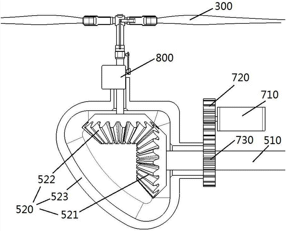
[0033] In the present disclosure, unless otherwise stated, the azimuth words used such as "up and down" generally refer to the upper and lower positions of the drone in the state of level flight. For details, please refer to image 3 "Front and rear" refers to the front and rear of the drone, and "inside and outside" refers to the contours of the corresponding parts. Furthermore, the terms "first", "second", etc., are used in this disclosure to distinguish one element from another and are not of order or importance.

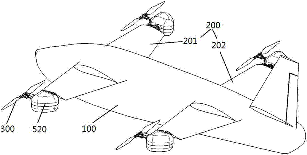
[0034] The tilt-rotor UAV provided by the present disclosure refers to setting a tiltable rotor on a fixed-wing aircraft, so that the UAV can switch be...


PUM


Abstract

The invention relates to a tilt rotor unmanned aerial vehicle. The tilt rotor unmanned aerial vehicle comprises a fuselage (100), a wing (200), a plurality of rotors (300) rotationally mounted on the wing, and a drive device (400) for driving the rotors (300), and a linkage assembly is connected between the rotors so that the rotors can rotate together. The number of the drive mechanism for driving the rotors to rotate is one, and the rotors are in linkage, so that the drive device can control multiple rotors at the same time, and the control strategy is simplified. In addition, since the number of the drive devices is one, the weight of a body of the unmanned aerial vehicle can be reduced, and thus the ability to load other equipment can be improved.

Description

technical field [0001] The present disclosure relates to the technical field of unmanned aerial vehicles, and in particular, to a tilt-rotor unmanned aerial vehicle. Background technique [0002] Tilt-rotor UAV is a unique aircraft that can take off, land, hover vertically like a helicopter, and fly forward at high speed like a fixed-wing aircraft. It combines the advantages of helicopters and fixed-wing propeller aircraft. The operator can realize various flight states of the tilt-rotor UAV by controlling the lift of each rotor. Each rotor needs to respond quickly in terms of lift according to the control of the flight control signal. In the rotor structure, each motor drives the rotor separately, and the tilting of the rotor is realized by tilting the steering gear. This structure is difficult to meet certain requirements for the use of UAVs in terms of load, range, and flight time. SUMMARY OF THE INVENTION [0003] The purpose of the present disclosure is to provide a...

Claims


Application Information

Patent Timeline
Patent Type & Authority Applications(China)
IPC IPC(8): B64C27/08B64C27/12B64D35/04
CPCB64C27/08B64C27/12B64D35/04
Inventor 苏文博杜春水梅森
Owner SHENYANG WOOZOOM TECH CO LTD
Why Eureka
Try Eureka