Waste heat collecting device for superhigh temperature shaft kiln feeding end

A technology of waste heat collection and feed end, which is applied in the direction of furnace control device, waste heat treatment, lighting and heating equipment, etc. It can solve the problems of easy blockage of waste heat collection device, low heat collection efficiency, easy to be oxidized and corroded, etc., to alleviate heat loss , Relieve dust blockage, solve the effect of easy erosion and aging

Inactive Publication Date: 2017-07-25
山东泰贝利尔环保科技有限公司
View PDF0 Cites 1 Cited by
  • Summary
  • Abstract
  • Description
  • Claims
  • Application Information

AI Technical Summary

Problems solved by technology

[0004] The purpose of the present invention is to provide a waste heat collection device for the feed end of an ultra-high temperature shaft kiln aiming at the technical defects of the prior art, so as to solve the problem that the heat collection efficiency of the waste heat collection device used for the feed end of a high temperature shaft kiln in the prior art is relatively low. low technical issues
[0005] Another technical problem to be solved by the present invention is that the waste heat collection device used for the feed end of the high-temperature shaft kiln in the prior art is easily oxidized and corroded inside under high-temperature conditions, and has a short service life.
[0006] Another technical problem to be solved by the present invention is that the waste heat collection device used for the feed end of the high-temperature shaft kiln in the prior art is easily blocked inside

Method used


Image

  • Waste heat collecting device for superhigh temperature shaft kiln feeding end

Examples


Embodiment 1

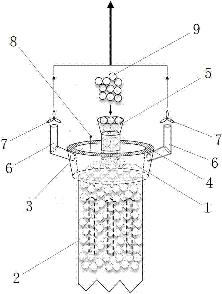
[0030] A waste heat collection device for the feed end of an ultra-high temperature shaft kiln, comprising a shell 1, a shaft kiln feed pipe 2, an end cover 3, a heat insulation layer 4, a feed hopper 5, an air induction pipe 6, a fan 7, a temperature Sensor 8, wherein the upper and lower ends of the housing 1 have a port respectively, the lower port of the housing 1 is connected with the nozzle of the shaft kiln feed pipe 2, the upper port of the housing 1 is connected with an end cover 3, and the outer circumference of the housing 1 Covered with a heat insulating layer 4, the air-introducing pipe 6 is fixedly connected to the housing 1, one end of the air-introducing pipe 6 extends into the interior of the housing 1, and the other is located outside the housing 1, and the air-introducing pipe 6 is located in the shell The port outside the body 1 is connected with a fan 7, the feed hopper 5 and the temperature sensor 8 are respectively connected to the end cover 3, the wide mo...

Embodiment 2

[0040] A waste heat collection device for the feed end of an ultra-high temperature shaft kiln, comprising a shell 1, a shaft kiln feed pipe 2, an end cover 3, a heat insulation layer 4, a feed hopper 5, an air induction pipe 6, a fan 7, a temperature Sensor 8, wherein the upper and lower ends of the housing 1 have a port respectively, the lower port of the housing 1 is connected with the nozzle of the shaft kiln feed pipe 2, the upper port of the housing 1 is connected with an end cover 3, and the outer circumference of the housing 1 Covered with a heat insulating layer 4, the air-introducing pipe 6 is fixedly connected to the housing 1, one end of the air-introducing pipe 6 extends into the interior of the housing 1, and the other is located outside the housing 1, and the air-introducing pipe 6 is located in the shell The port outside the body 1 is connected with a fan 7, the feed hopper 5 and the temperature sensor 8 are respectively connected to the end cover 3, the wide mo...


PUM


Abstract

The invention provides a waste heat collection device for the feed end of an ultra-high temperature shaft kiln. In this technical proposal, a shell for heat collection is added at the port of the feed pipe of the conventional shaft kiln, and the heat radiating upward from the port is eliminated. The heat plays the role of blocking and collecting. The invention covers the outer periphery of the shell with a heat insulation layer, which can maintain the heat in the shell and effectively improve the recovery rate of waste heat; The wind is guided into the shell, and then transported to the outside through the air duct, which helps to alleviate the problem of material dust blocking. The feed hopper located at the upper end cover is used to add materials into the shaft kiln, and the large and small structure of the feed hopper also helps to alleviate heat loss. The temperature sensor located on the end cover can monitor the internal temperature of the shell, and can cooperate with the control system to control the fan speed according to the temperature. The invention has outstanding innovation and remarkable technical effect.

Description

technical field [0001] The invention relates to the technical field of supporting devices for a high-temperature shaft kiln, in particular to a waste heat collection device used at the feed end of an ultra-high-temperature shaft kiln. Background technique [0002] Shaft kiln refers to a vertical continuous kiln consisting of a steel shell with a vertical axis and a refractory brick lining, used for firing bulk bulk materials. Usually liquid or solid fuel is used, and the thermal efficiency is higher than that of tunnel kiln. It is widely used in the domestic refractory industry at present. [0003] Because the internal temperature of the shaft kiln is very high, it will naturally radiate heat to the outer periphery. This heat dissipation effect is especially obvious at the open feed port. If the heat is not collected, it will waste energy on the one hand and cause The temperature of the feed port is too high, which will affect the operating state and service life of the sur...

Claims


Application Information

Patent Timeline
Patent Type & Authority Applications(China)
IPC IPC(8): F27B1/00F27B1/20F27B1/26F27B1/28F27D17/00F27D19/00
CPCF27B1/00F27B1/20F27B1/26F27B1/28F27D17/004F27D19/00F27D2019/0025
Inventor 张会友刘辉张立伟
Owner 山东泰贝利尔环保科技有限公司
Why Eureka
Try Eureka