Piezoelectric fiber-based inertia driving device

A piezoelectric fiber and inertial drive technology, applied in the direction of piezoelectric effect/electrostrictive or magnetostrictive motors, generators/motors, electrical components, etc., to reduce complexity and overcome the effects of difficult control

Inactive Publication Date: 2017-07-25
JILIN UNIV
View PDF8 Cites 0 Cited by
  • Summary
  • Abstract
  • Description
  • Claims
  • Application Information

AI Technical Summary

Problems solved by technology

[0005] The technical problem to be solved in the present invention is: the piezoelectric fiber (2) is elongated and deformed under the excitation of the electric signal, and the metal plate (3) is driven to drive the upper mass block 1 (1) to swing, and the swing process of the mass block 1 (1) is used to The inertial impact force generated in the device realizes the overall movement of the device

Method used


Image

  • Piezoelectric fiber-based inertia driving device
  • Piezoelectric fiber-based inertia driving device
  • Piezoelectric fiber-based inertia driving device

Examples


Embodiment Construction

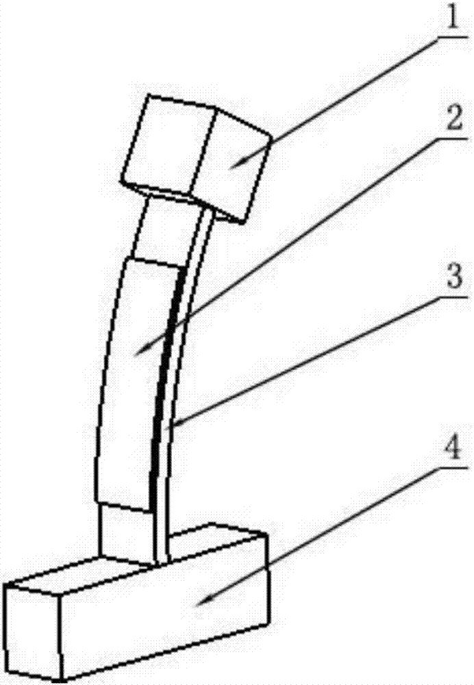
[0017] The invention relates to an inertial drive device based on piezoelectric fibers, which is a new type of drive device that utilizes the inverse piezoelectric effect of piezoelectric fibers and the principle of inertial drive to drive a mechanism to realize motion. like figure 1 As shown, the metal plate (3) pre-bent to a certain radian is bonded with the piezoelectric fiber (2) to form an actuator, and the two ends of the metal plate (3) are respectively connected to mass block 1 (1) and mass block 2 (4) , wherein the mass block 2 (4) plays a stabilizing and supporting role, and the mass block 1 (1) generates inertial force during the movement. The piezoelectric fiber and the metal plate are bonded in parallel with conductive glue. The metal plate (3) is processed into a certain radian, and the end is processed into a threaded column to connect the mass block 1 (1) and the mass block 2 (4), and the mass block 1 (1) and the mass block 2 (4) have corresponding threaded ho...


PUM


Abstract

The invention relates to an inertial drive device based on piezoelectric fibers, including an actuator and two masses. The actuator is composed of a piezoelectric fiber and a metal plate that is pre-bent to a certain radian. The piezoelectric fiber is elongated and deformed under the action of an alternating voltage, causing a bending moment on the surface of the metal plate. Two mass blocks are connected at both ends of the metal plate. , the mass block below plays a role of stability and support, and the mass block above generates inertial force during the movement. Under the excitation of the electric signal, the piezoelectric fiber elongates and deforms, and the metal plate drives the upper mass block to swing to the right quickly, generating an inertial impact force to the left, and the device moves to the left as a whole, and then changes the input electrical signal, the metal plate recovers, and the upper mass The block moves to the left, and the device returns to its original state, completing one motion cycle. By changing the form of the input electrical signal, the device can also be moved to the right. The invention has the advantages of simple structure, easy realization, high device reliability, easy generation and control of excitation signals and the like.

Description

technical field [0001] The invention belongs to the field of precision mechanical drive. It is used in micro-robot drive, micro-miniature machinery, etc. Background technique [0002] In recent years, with the rapid development of micro-nano technology, there is a demand for micro-mechanical drive technology in the technical fields of biomedical engineering, precision machinery, robots, computers, automatic control, precision measurement, micro-manufacturing of precision devices, and ultra-precision machining. increasing day by day. As the core of micro-actuation technology, micro-actuation technology has become the focus of attention under this demand. Traditional precision drive mainly adopts mechanical type, such as precision screw pair, rolling slide guide rail, precision spiral wedge mechanism, etc., but due to the existence of gaps, friction, crawling and other problems, its precision is difficult to meet the requirements. Under this condition, the developed Many ne...

Claims


Application Information

Patent Timeline
Patent Type & Authority Applications(China)
IPC IPC(8): H02N2/02
CPCH02N2/025
Inventor 董景石刘畅曹义朱晓刚徐智吴越杨志刚赵宏伟
Owner JILIN UNIV
Why Eureka
Try Eureka