Self-cleaning centrifuge with centralized lubrication device

A centralized lubrication and centrifuge technology, applied in the field of centrifuges, can solve the problems of cumbersome refueling operation, asynchronous bearing lubrication, affecting the centrifugal effect, etc., and achieve the effect of improving the centrifugal effect and simplifying the operation.

Inactive Publication Date: 2017-07-28
ANHUI PUYUAN SEPARATION MACHINERY MFG CO LTD
View PDF8 Cites 2 Cited by
  • Summary
  • Abstract
  • Description
  • Claims
  • Application Information

AI Technical Summary

Problems solved by technology

In the existing centrifuges, in order to prevent the drum from being scratched, a safe distance is reserved between the scraper and the drum wall, which makes the filter cake of a certain thickness always remain in the drum when the scraper completes scraping. on the wall, affecting its centrifugal effect
Moreover, in the existing centrifuges, the lubrication of the bearings on the main shaft for driving the drum rotation is not synchronous, and the refueling operation is very cumbersome.

Method used


Image

  • Self-cleaning centrifuge with centralized lubrication device
  • Self-cleaning centrifuge with centralized lubrication device
  • Self-cleaning centrifuge with centralized lubrication device

Examples


Embodiment Construction

[0022] Hereinafter, the technical solution of the present invention will be described in detail through specific embodiments.

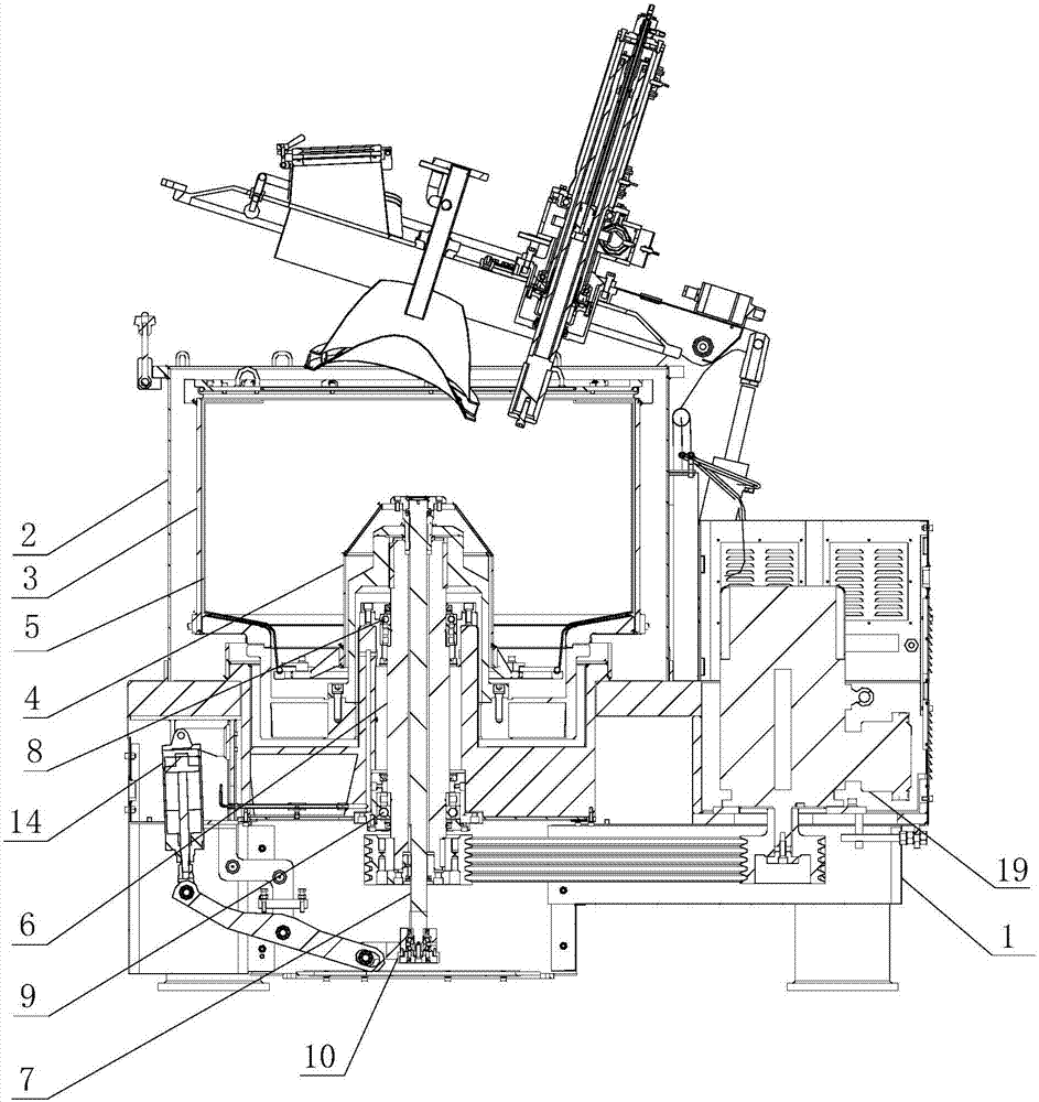
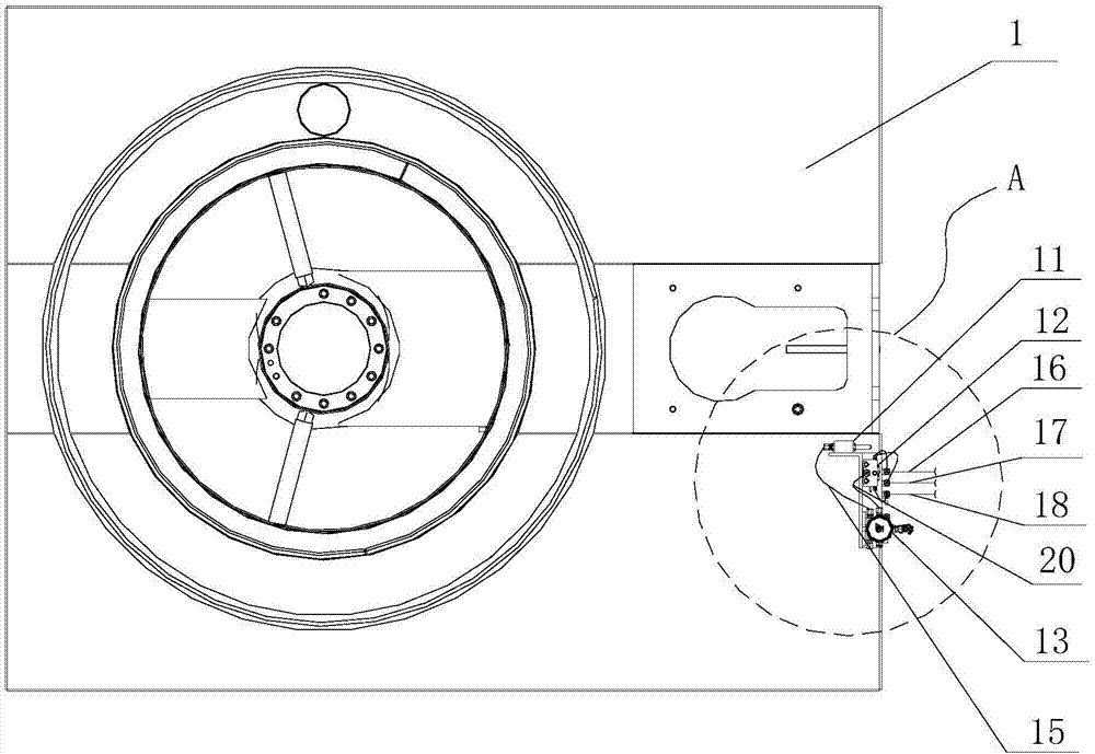
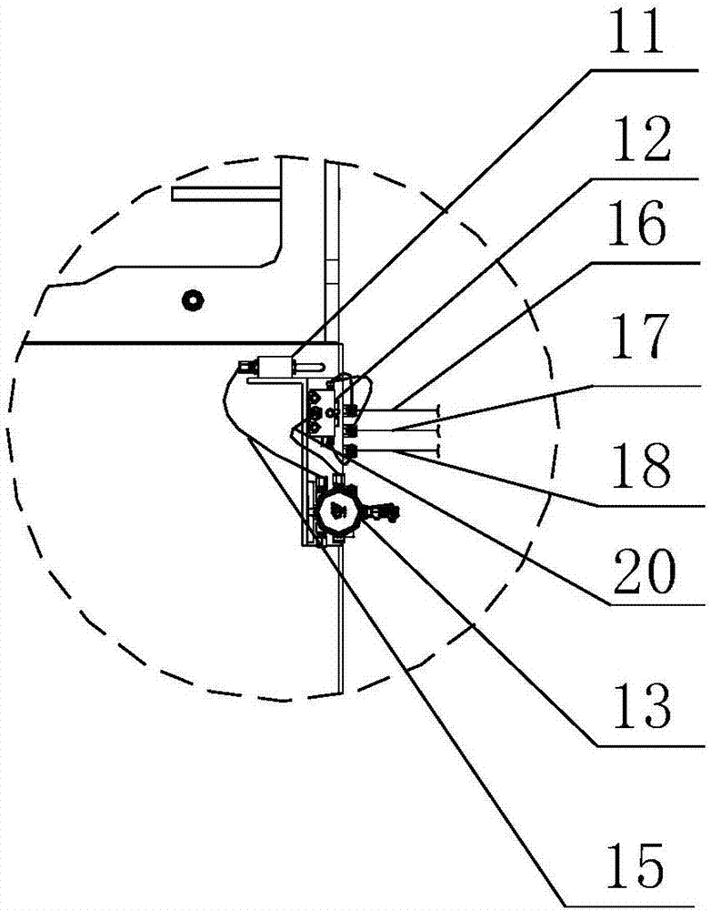
[0023] Such as Figure 1-3 As shown, figure 1 It is a schematic structural diagram of a self-cleaning centrifuge with a centralized lubrication device proposed by the present invention; figure 2 It is a schematic diagram of the structure of the centralized lubrication device in a self-cleaning centrifuge with a centralized lubrication device proposed by the present invention; image 3 for figure 2 Enlarged view at center A.

[0024] Reference Figure 1-3 , The self-cleaning centrifuge with centralized lubrication device proposed by the embodiment of the present invention includes: a centrifuge body and a centralized lubrication device, wherein:

[0025] The centrifuge body includes a base 1, a casing installed on the base 1, a rotating drum 3 installed inside the casing 2, a lifting cover 4 located at the lower end of the rotating drum 3, and an upper end...


PUM


Abstract

The invention discloses a self-cleaning centrifuge with a centralized lubricating device, comprising: a centrifuge body and a centralized lubricating device, wherein: the centrifuge body includes a machine base, a casing installed on the The drum, the lifting cover located at the lower end of the drum, the filter bag located inside the drum, the main shaft used to drive the drum to rotate, and the lifting shaft that is axially fixed and radially slidable with the main shaft, and the upper end bearing and the lower end bearing are installed on the main shaft; The lifting shaft is connected with a rotary joint; the lubricating device includes an oil filter, an oil separator and a refueling pump; the refueling pump has an oil inlet and an oil outlet, the oil inlet is connected to the oil filter, and the oil outlet is connected to the oil separator Connected; the oil separator is connected with the second pipeline, the third pipeline and the fourth pipeline, and the ports of the second pipeline, the third pipeline and the fourth pipeline are located at the positions of the upper end bearing, the lower end bearing and the rotary joint respectively. The invention can achieve the purpose of simplifying operation and synchronous centralized lubrication.

Description

Technical field [0001] The invention relates to the technical field of centrifuges, in particular to a self-cleaning centrifuge with a centralized lubrication device. Background technique [0002] A centrifuge is a machine that uses centrifugal force to accelerate the separation of different materials that need to be separated. Centrifuge is widely used in chemical, petroleum, food, pharmaceutical, mineral processing, coal, water treatment and shipbuilding sectors. In order to prevent the drum from scratching in the existing centrifuge, a safe distance is reserved between the scraper and the wall of the drum, which makes the scraper every time the scraping is completed, a certain thickness of filter cake will always remain on the drum. On the wall, affecting its centrifugal effect. Moreover, in the existing centrifuge, the lubrication of the bearings on the main shaft for driving the rotating drum to rotate is not synchronized, and the refueling operation is very complicated. ...

Claims


Application Information

Patent Timeline
IPC IPC(8): B04B7/16B04B9/08B04B15/06
CPCB04B7/16B04B9/08B04B15/06
Inventor 沈云翔王世亮胡守志戚全利罗潇张琼
Owner ANHUI PUYUAN SEPARATION MACHINERY MFG CO LTD
Why Eureka
Try Eureka