

Flue gas waste heat recovery device
A technology for recycling device and flue gas waste heat, which is applied in drying gas arrangement, heat exchanger, indirect heat exchanger, etc., to achieve the effect of prolonging the time of waste heat, saving production cost and saving energy.
- Summary
- Abstract
- Description
- Claims
- Application Information
AI Technical Summary
Problems solved by technology
Method used
Image

Examples
Embodiment Construction
[0033] The technical solutions in the present invention will be clearly and completely described below in conjunction with the accompanying drawings in the embodiments of the present invention. Obviously, the described embodiments are only some, not all, embodiments of the present invention. Based on the embodiments of the present invention, all other embodiments obtained by persons of ordinary skill in the art without making creative efforts belong to the protection scope of the present invention.
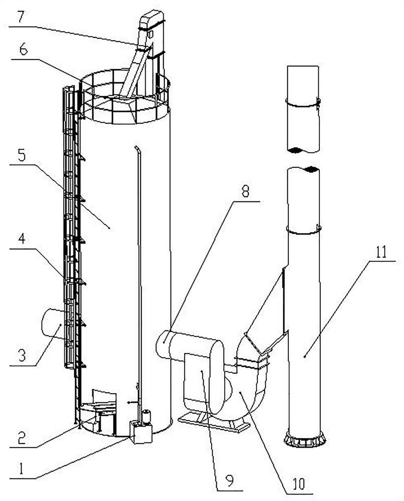
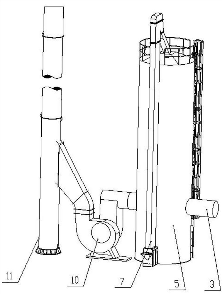
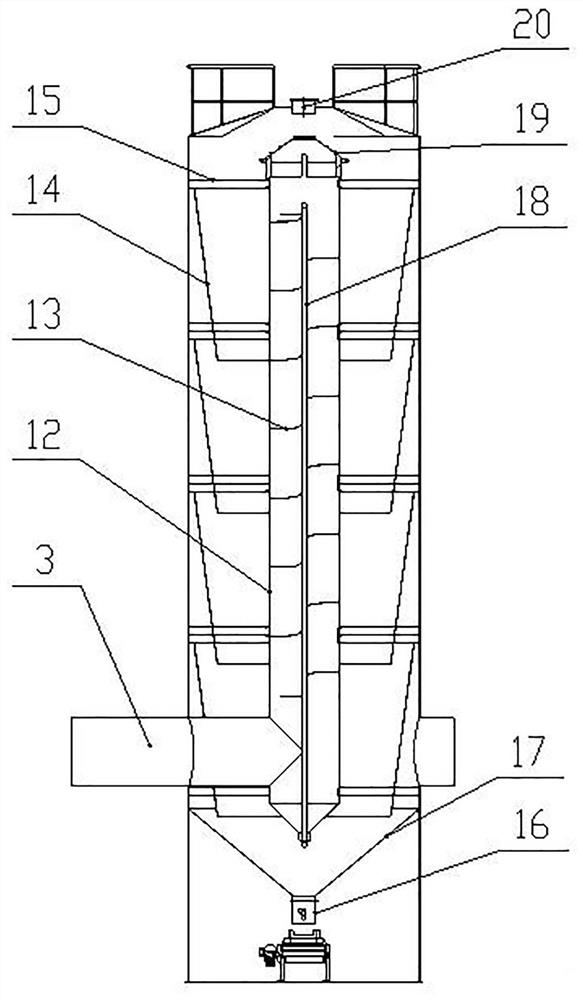
[0034] Such as Figure 1-5 As shown, the present invention provides a technical solution: a flue gas waste heat recovery device, including an outer shell 5, a vertical inner air duct 12 arranged inside the outer shell, and a circulating water system 1. In a negative pressure working environment, the outer shell One side of the body 5 is provided with an air inlet pipe 3, which directly communicates with the bottom of the vertical inner air duct 12, and the other side of the outer ...
PUM
 Abstract
Description
Claims
Application Information