Braking clutch structure of lever block

A lever hoist, clutch device technology, applied in the directions of portable lifting devices, hoisting devices, etc., can solve the problems of heavy objects falling, hidden safety hazards and high safety risks of braking and clutch devices, etc.

Active Publication Date: 2017-07-28
维多利科技(江苏)有限公司
View PDF8 Cites 1 Cited by
  • Summary
  • Abstract
  • Description
  • Claims
  • Application Information

AI Technical Summary

Problems solved by technology

Chinese invention patent CN204917784 U discloses a lever block. The lever block of this structure includes a front wall panel and a rear wall panel, a clutch device and a wrench device, but the brake and clutch device have certain safety hazards. If the main braking system fails, it will cause heavy objects to fall, which is a great safety risk

Method used


Image

  • Braking clutch structure of lever block
  • Braking clutch structure of lever block
  • Braking clutch structure of lever block

Examples


Embodiment Construction

[0021] The standard parts used in the present invention can be purchased from the market, and the special-shaped parts can be customized according to the instructions and the accompanying drawings. The specific connection methods of each part adopt mature bolts, rivets, welding in the prior art , pasting and other conventional means, no longer described in detail here.

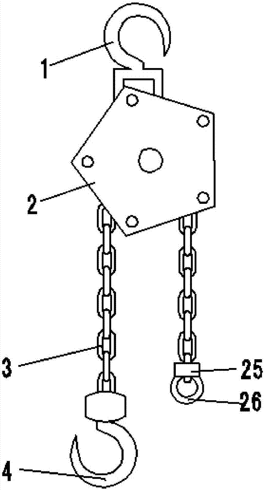
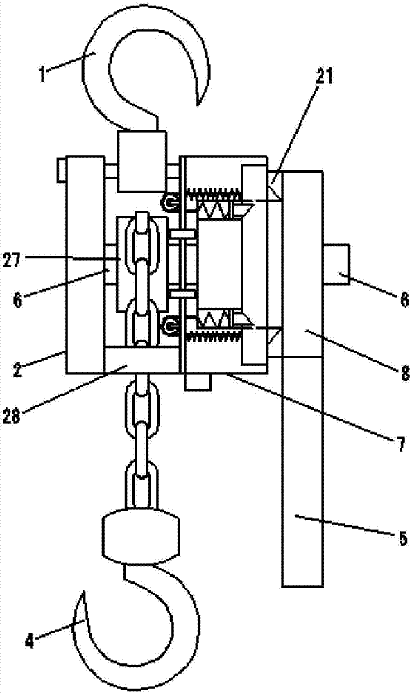
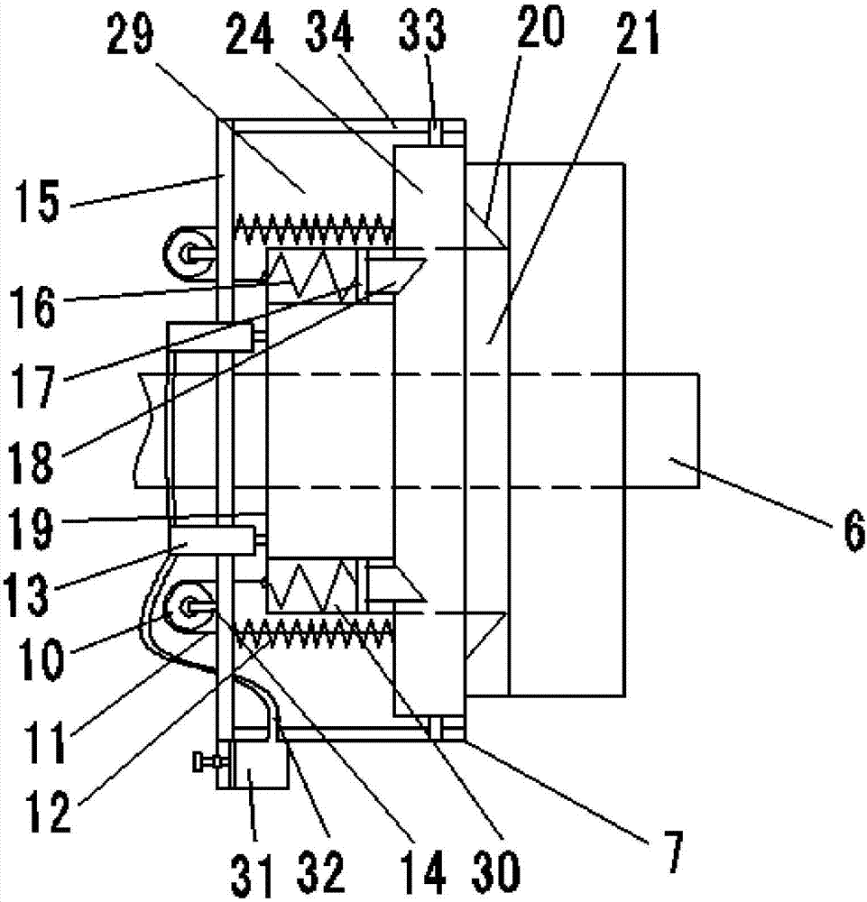
[0022] refer to Figure 1-7, a specific embodiment of the present invention includes a front wall panel 7, a rear wall panel 2 and a long axis 6, and a clutch device 8 is connected to the position on the front side of the front wall panel 1 on the long axis 4, and the inside of the clutch device 8 A circular limiting plate 21 is also provided, and the inner side of the limiting plate 21 is circularly arranged with several convex ribs 22, gaps 23 are arranged between the convex ribs 22, and the convex ribs 22 are in selective contact with the front wallboard 7, so The inside of the front wallboard 7 is provide...


PUM


Abstract

The invention discloses a braking clutch structure of a lever block. A circular limiting plate is arranged in a clutch device, a convex edge is arranged on the limiting plate, and a first cavity and a back plate are arranged in a front wall plate. A fixed pulley is arranged on the back plate, a second annular ring is arranged in the first cavity, and a first spring is arranged between the second annular ring and the back plate. A second wedge-shaped block is arranged on the second annular ring, a first annular ring is inserted into the second annular ring, and a plurality of second cavities are annularly distributed in the first annular ring. The interior of the first annular ring is connected with a first piston and a first wedge-shaped block through a second spring, the first annular ring and the second annular ring are mutually connected through two steel ropes, and the steel ropes wind across the fixed pulley. Two hydraulic cylinders are further fixed to the back plate, piston rods of the two hydraulic cylinders make contact with the positions above and below the first annular ring correspondingly, the protruding direction of the first wedge-shaped block is opposite to that of the second wedge-shaped block, and the first wedge-shaped block and the second wedge-shaped block are selectively located in gaps. According to the braking clutch structure of the lever block, the defects in the prior art can be improved, and the better fall-proof effect is achieved.

Description

technical field [0001] The invention relates to the technical field of lifting equipment, in particular to a brake clutch structure of a lever block. Background technique [0002] The lever hoist is manually pulled by the wrench, and with the help of the principle of leverage, it can obtain a linear traction that matches the load, so as to drive the weight to move up and down. Due to the small size and light weight of the lever block, it is very convenient to carry and operate, and is suitable for heavy objects of small tonnage. The existing lever hoist mainly adopts a brake ratchet, a friction plate, a reversing ratchet, and a positioning part on the long axis in sequence. The reversing ratchet and the long axis are connected by threads. The reversing pawl on the wrench meshes with the reversing ratchet. When the wrench is pulled, the reversing ratchet can be driven to rotate by the wrench. Along with the axial movement, the friction plate is pressed, and the brake ratche...

Claims


Application Information

Patent Timeline
Patent Type & Authority Applications(China)
IPC IPC(8): B66D5/28B66D5/32B66D3/12
CPCB66D3/12B66D5/28B66D5/32
Inventor 张景东
Owner 维多利科技(江苏)有限公司
Why Eureka
Try Eureka