Gas condensate separation device and technical method

A separation device and process method technology, applied in the petroleum industry, hydrocarbon oil distillation control/regulation, hydrocarbon distillation and other directions, can solve the problems of short processing flow, limited investment capacity and management level, etc., to achieve low overall cost and reduce one time The effect of cost-effective investment and shortening of the process flow

Active Publication Date: 2017-07-28
BEIJING PETROCHEM ENG
View PDF0 Cites 5 Cited by
  • Summary
  • Abstract
  • Description
  • Claims
  • Application Information

AI Technical Summary

Problems solved by technology

However, for private owners in Southeast Asia who are only in their infancy, their investment capabilities and m...

Method used


Image

  • Gas condensate separation device and technical method
  • Gas condensate separation device and technical method
  • Gas condensate separation device and technical method

Examples


Embodiment Construction

[0021] It should be noted that, in the case of no conflict, the embodiments in the present application and the features in the embodiments can be combined with each other. The present invention will be described in detail below with reference to the accompanying drawings and examples.

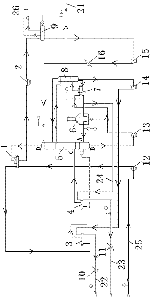
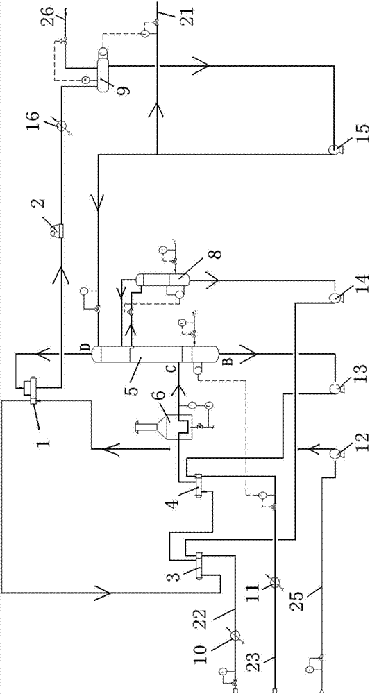
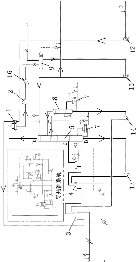
[0022] A condensate oil separation device, comprising an atmospheric tower 5, an atmospheric tower top gas heat exchanger 1, an atmospheric tower top air cooler 2, a tower top reflux tank 9, a tower top reflux pump 15, and a tower top naphtha cooling Device 16, atmospheric tower bottom oil pump 13, side stripper reboiler 7, side stripper 8 and atmospheric tower reboiler 6; atmospheric tower bottom oil pump 13, side stripper reboiler 7 and side line The stripping tower 8 is connected successively, and the bottom oil pump 13 of the atmospheric tower is also connected with the bottom oil outlet B of the atmospheric tower 5, the air heat exchanger 1 at the top of the normal pressure tower, the air ...


PUM


Abstract

The invention discloses a gas condensate separation device and a technical method. According to the gas condensate separation device, normal pressure tower bottom oil is subjected to pressure increasing using a pump firstly, and then is delivered into a side stripper reboiler as a heat source of the side stripper reboiler; at the same time, normal pressure tower undercooling feeding is adopted, wherein raw material gas condensate is subjected to heat exchange with fractionation products, and then is delivered into the normal pressure tower directly for heat exchanged of loaded materials in a tower, so that heat exchanged equipment is reduced, and dependence on common auxiliary heat sources is reduced, heat source concentration is capable of increasing heat efficiency, and reducing energy consumption, and equipment investment is reduced; and in addition, normal pressure tower top gas is delivered through a tower top gas heat exchanger, is cooled using a normal pressure tower top air cooler, and is delivered into a normal pressure tower top return tank directly, so that the operation temperature in the normal pressure tower top return tank is relatively high, more noncondensable gas is released, the saturated vapor pressure of tower top naphtha is reduced; a tower top water cooler is arranged on the tower top return tank, so that the operation pressure of the tower top noncondensable gas is higher, and it is more convenient for outer transportation.

Description

technical field [0001] The invention relates to the technical field of petrochemical industry, in particular to a condensate oil separation device and a condensate oil separation process. Background technique [0002] Condensate oil refers to the liquid phase components condensed from condensate gas fields or associated natural gas in oil fields, also known as natural gasoline. Its main component is a mixture of C5 to C11+ hydrocarbons, which is lighter than crude oil, and its fractions are mostly at 20°C to 260°C. In addition, because the output is lower than that of crude oil, the processing scale is usually smaller and the process is shorter. Domestic condensate separation devices are mostly obtained from atmospheric distillation devices. Utilities and auxiliary systems rely on old crude oil plants, and fuel gas and steam are readily available. The existing condensate separation process is steam stripping. Such as figure 2 and heat conduction oil system heating method ...

Claims


Application Information

Patent Timeline
IPC IPC(8): C10G7/00C10G7/12
CPCC10G7/00C10G7/12
Inventor 李奎闫东菊董小平南春祥彭坚崔慧刘戈曹坚
Owner BEIJING PETROCHEM ENG
Why Eureka
Try Eureka