Yarn feeding control method of circular-weft knitting machine

A circular knitting machine and control method technology, applied in knitting, weft knitting, textiles and papermaking, etc., can solve problems such as troublesome wiring, loose weaving structure, yarn disorder, etc., achieve fast and timely actions, and ensure stability , Yarn tidy effect

Active Publication Date: 2017-07-28
泉州威廉针织科技研究院股份有限公司
View PDF7 Cites 11 Cited by
  • Summary
  • Abstract
  • Description
  • Claims
  • Application Information

AI Technical Summary

Problems solved by technology

[0004] Some of the existing yarn feeders are also equipped with a clutch mechanism. The clutch mechanism is charged by the electronic control system to perform clutch control on the rotation of the yarn feeder. The clutch cooperates with the distributor to realize the wiring action, and the discarded yarn is wired The machine is cut off and stuck, and the clutch acts at the same time to stop yarn storage and yarn feeding. However, due to the influence of the rotational inertia, the wire delivery wheel needs to continue to rotate several times (or even more) after the clutch acts to slow down and stop. This lagging stop is inevitable. It will greatly affect the improvement of weaving efficiency and bring a lot of trouble to wiring
Due to the defects of the yarn feeder itself, when changing the yarn and weaving, it will often lead to the disorder of the yarn. In the next weaving, there will be bad conditions such as starting thread and loose weaving structure, which will seriously affect the quality and efficiency of weaving work.

Method used


Image

  • Yarn feeding control method of circular-weft knitting machine

Examples


Embodiment Construction

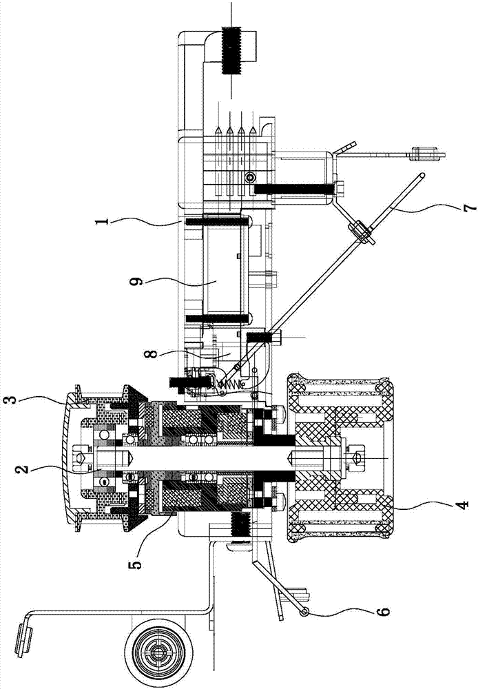
[0014] Attached below figure 1 The present invention is further described.

[0015] Such as figure 1 As shown, it is a yarn feeder, which includes a body 1 and a transmission shaft 2 disposed on the body 1, a synchronous wheel 3 disposed on the transmission shaft 2, a wire transmission wheel 4 disposed on the transmission shaft 2, and a The clutch brake 5 on the body 1, the front probe rod 6 and the rear probe rod 7 on the body 1, and the photoelectric sensor 8 on the body 1, when the clutch brake 5 is in the clutch state, press the transmission wheel 4 , make it stop, when the clutch brake 5 is energized, the clutch brake 5 is engaged, thereby unclamping the transmission wheel 4, and the transmission wheel 4 realizes normal operation.

[0016] According to the above-mentioned yarn feeder, the first embodiment provides a method for controlling yarn feeding of a circular knitting machine, comprising the following steps:

[0017] When the yarn needs to be changed according t...


PUM


Abstract

The invention relates to a yarn feeding control method of a circular-weft knitting machine. The yarn feeding control method of the circular-weft knitting machine is characterized in that the method includes the following steps that 1, yarn feeding machines of the circular-weft knitting machine are all provided with control chips and numbered, all control chips are connected with a host through a network formed by CAN communication buses, and each yarn feeding machine includes a machine body, a yarn transporting wheel and a clutch brake, wherein the yarn transporting wheel is arranged on the machine body, and the clutch brake is arranged in the machine body and used for controlling the yarn transporting wheel; 2, when yarn needs to be fed discontinuously, the host sends a motion command to the yarn feeding machine with a corresponding number in advance, after receiving the motion command, the yarn feeding machine with the corresponding number immediately draws the clutch brake, a clutch plate is drawn, brake coils obtain power at the same time, a brake pad is loosened, a brake is in a non-braking state, and the yarn feeding machine synchronously rotates to feed yarn; meanwhile, the brake coils of the yarn feeding machine corresponding to yarn which is temporarily out of service lose power, the clutch plate is separated, the yarn feeding machine loses rotary power, the brake coils lose power and draw the brake pad at the same time, the brake is in a braking state, and the yarn feeding machine stops feeding the yarn.

Description

technical field [0001] The invention relates to a yarn feeding control method for a circular knitting machine. Background technique [0002] The yarn feeder is an important part of the circular knitting machine. The yarn feeder mainly includes the shell, the main shaft and the wire delivery wheel installed on it. The yarn pressure ring and the tension ring are sleeved on the yarn delivery wheel. At the center of the circle, the main shaft drives the yarn delivery wheel to rotate for yarn storage. Yarn storage means that yarn is fed into the yarn and stored on the wire delivery wheel, and yarn delivery is that the yarn is output from the wire delivery wheel through the tension ring. In the production of high-quality weft-knitted fabrics, in order to control the size of the knitting loops and stabilize the yarn tension during weaving, it is necessary to equip a yarn feeding device to ensure the quality of the yarn feeding. The types of yarn feeding devices currently available...

Claims


Application Information

Patent Timeline
Patent Type & Authority Applications(China)
IPC IPC(8): D04B15/48D04B35/14
CPCD04B15/484D04B35/14
Inventor 刘明举邓才参王欣宇
Owner 泉州威廉针织科技研究院股份有限公司
Why Eureka
Try Eureka