Displacement enlarging friction damper and assembly construction process

A friction damper, a large-scale technology, applied in the direction of building types, building components, earthquake resistance, etc., can solve the problems of affecting building use functions, low lever transmission efficiency, inconvenient installation and construction, etc., to achieve easy maintenance and replacement, stable working performance, Create handy effects

Pending Publication Date: 2017-07-28
HEBEI UNIV OF TECH +1
View PDF1 Cites 12 Cited by
  • Summary
  • Abstract
  • Description
  • Claims
  • Application Information

AI Technical Summary

Problems solved by technology

The displacement of the existing damper during operation is usually equal to the relative displacement of the connection point, so the damper should be installed in a position where the relative deformation of the structure is relatively large. If the relative deformation of the structure is small, the damper cannot effectively perform its energy dissipation function due to the small displacement
For this reason, scholars have developed a new technology to make the displacement of the damper greater than the rel

Method used


Image

  • Displacement enlarging friction damper and assembly construction process
  • Displacement enlarging friction damper and assembly construction process
  • Displacement enlarging friction damper and assembly construction process

Examples


Example Embodiment

[0028] The present invention will be further described below in conjunction with the drawings.

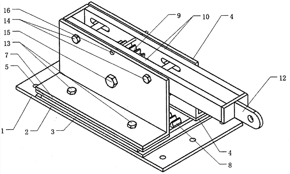
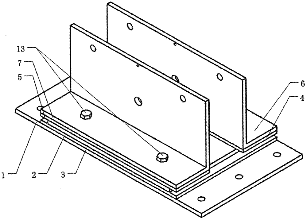
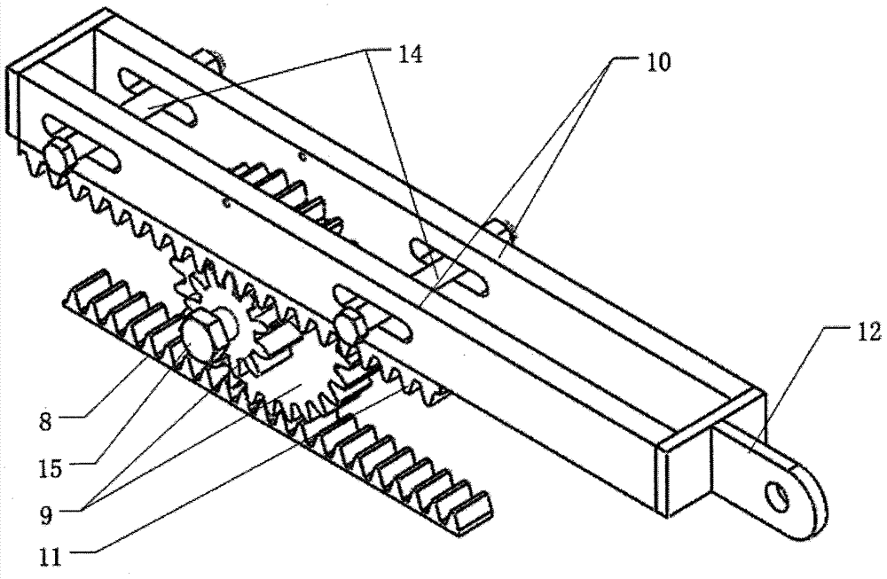
[0029] according to figure 1 with image 3 As shown, the displacement-amplified friction damper includes the lower connecting plate 1, the lower friction plate 2, the main plate 3, the upper rear friction plate 4, the upper front friction plate 5, the rear angle steel 6, the front angle steel 7, the lower rack 8, and the triple The gear 9, the double link 10, the upper rack 11, the U-shaped connecting piece 12, the high-strength bolt 13, the limit bolt 14, the gear shaft 15 and the positioning pin 16.

[0030] according to figure 2 , Figure 4 , Figure 5 , Image 6 , Figure 7 , Figure 8 , Picture 9 with Picture 10 As shown, two high-strength bolts 13 pass through the rear angle steel bolt hole 903, the upper and rear friction plate bolt hole 701, the main board slotted hole 601, the lower friction plate bolt hole 501, and the lower connecting plate bolt hole 401, and the other two ...


PUM


Abstract

The invention belongs to the technical field of civil engineering and relates to a displacement enlarging friction damper and the assembly construction process. The displacement enlarging friction damper comprises a lower connecting plate, a lower friction piece, a main plate, an upper rear friction piece, an upper front friction piece, a rear steel angle, a front steel angle, lower racks, triple gears, dual connecting rods, upper racks, U-shaped connecting pieces, a high-strength bolt, a limiting bolt, a gear rotary shaft and a positioning pin. The main plate is located between the lower connecting plate and the front steel angle and the rear steel angle which are arranged in a separated mode. The lower friction piece is adhered to the upper surface of the lower connecting plate. The two friction pieces are adhered to the lower surface of the rear steel angle and the lower surface of the front steel angle correspondingly. The triple gears, the upper racks, the lower racks and the dual connecting rods are located between the rear steel angle and the front steel angle. The lower racks are welded to the upper surface of the main plate, and the upper racks are welded to the lower surfaces of the dual connecting rods. The U-shaped connecting pieces are welded to the ends of the dual connecting rods. The sliding friction displacement of the damper is enlarged by the displacement enlarging friction damper through the gear transmission theory, and the energy consumption capacity is high.

Description

technical field [0001] The invention belongs to the technical field of civil engineering, and relates to an energy dissipation and shock absorbing device, in particular to a friction damper which provides amplified displacement through gears. Background technique [0002] Energy dissipation and shock absorption technology is to connect dampers in parallel in the lateral force-resistant members of the structure, and the dampers consume most of the seismic energy to ensure the safety of the main structure. It is an active and effective anti-seismic strategy. The displacement of the existing damper during operation is usually equal to the relative displacement of the connection point, so the damper should be installed in a position where the relative deformation of the structure is relatively large. If the relative deformation of the structure is small, the damper cannot effectively perform its energy dissipation function due to the small displacement . For this reason, schola...

Claims


Application Information

Patent Timeline
IPC IPC(8): E04H9/02E04B1/98
CPCE04H9/021
Inventor 任文杰吴书良王利强
Owner HEBEI UNIV OF TECH
Why Eureka
Try Eureka