Intercooling type multistage axial flow air compressor and working method thereof

An axial flow compressor, cold type technology, applied in axial flow pumps, mechanical equipment, non-variable pumps, etc., can solve problems that cannot be used to reduce power consumption, complex structure, and pressure loss of low-pressure compressors, and achieve Effects of avoiding compression power consumption, avoiding pressure loss, and reducing compression power consumption

Pending Publication Date: 2017-07-28
HUANENG POWER INTERNATIONAL +1
View PDF9 Cites 10 Cited by
  • Summary
  • Abstract
  • Description
  • Claims
  • Application Information

AI Technical Summary

Problems solved by technology

The intercooling technology of the existing compressor requires a large space and complex structure, so it can only be applied between the low-pressure compressor and the high-pressure compressor of the gas turbine in a power station or a ship's gas turbine
Although the above technology can reduce the power consumption of the high-pressure compressor to a certain extent, it cannot be used to reduce the power consumption of the low-pressure compressor, and the fluid flowing through the intercooling channel will inevitably bring a certain pressure loss

Method used


Image

  • Intercooling type multistage axial flow air compressor and working method thereof
  • Intercooling type multistage axial flow air compressor and working method thereof

Examples


Embodiment Construction

[0021] The present invention is described in further detail below in conjunction with accompanying drawing:

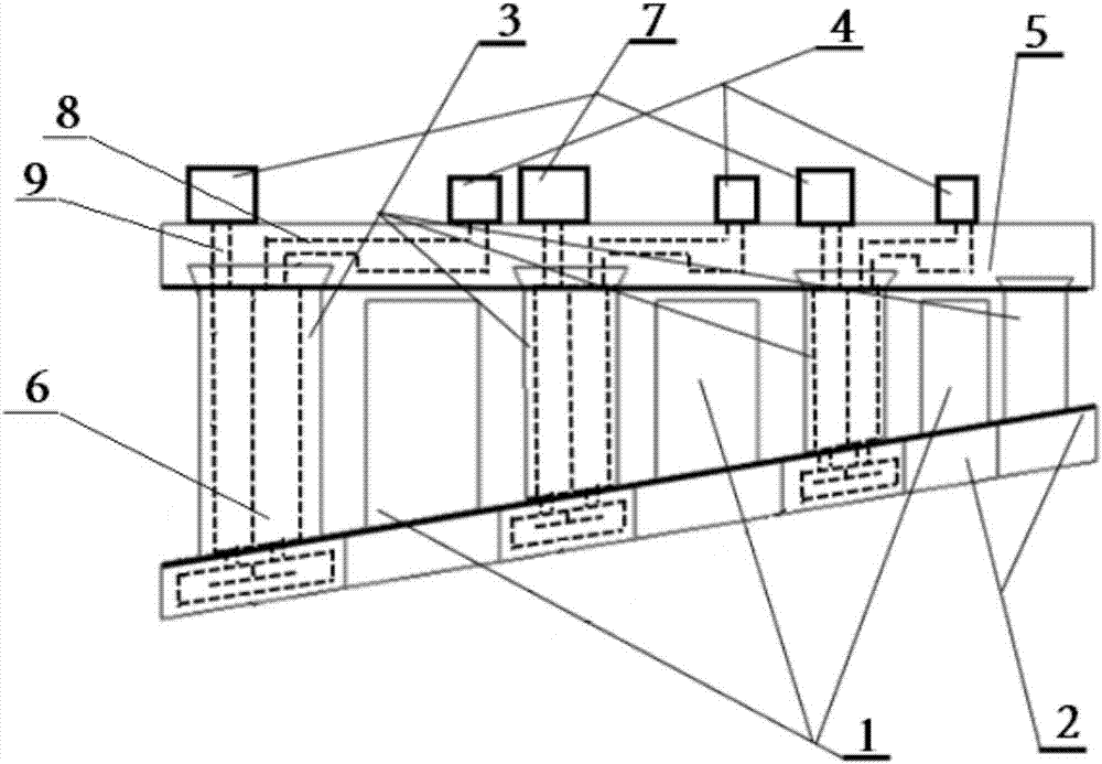
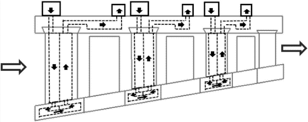
[0022] refer to figure 1 , the intercooled multi-stage axial flow compressor of the present invention includes a casing 5, a hub 2, a plurality of rotor blades 1 and a plurality of stator blades 3, and each rotor blade 1 and each stator blade 3 are sequentially staggered along the direction of flow of the working medium distribution, and the lower end of the rotor blade 1 is connected to the hub 2, the upper end of the stator blade 3 is connected to the casing 5, the lower end of the stator blade 3 is movably connected to the hub 2, and the casing 5 is provided with a number of cold air intake ring chambers 7 And some cold air exhaust ring chambers 4, a number of first internal cooling runners 8 and a number of second internal cooling runners 9 are opened in the casing 5, a third internal cooling runner 6 is provided in the 3 stator blades, a static The leaves 3 corre...


PUM


Abstract

The invention discloses an intercooling type multistage axial flow air compressor and a working method thereof. The lower ends of movable vanes are connected with a hub. The upper ends of static vanes are connected with a casing. The lower ends of the static vanes are movably connected with the hub. Multiple cold air inlet ring cavities and multiple cold air exhaust ring cavities are formed in the casing. Multiple first inner cooling runners and multiple second inner cooling runners are arranged in the casing. A third inner cooling runner is arranged in each static vane. Each static vane corresponds to one cold air inlet ring cavity, one cold air exhaust ring cavity, one first inner cooling runner and one second inner cooling runner. A cooling medium outlet of each cold air inlet ring cavity communicates with a cooling medium inlet of the corresponding cold air exhaust ring cavity through the corresponding first inner cooling runner, the third inner cooling runner in the corresponding static vane and the corresponding second inner cooling runner in sequence. According to the multistage axial flow air compressor and the working method thereof, power consumption of the air compressor can be reduced, and pressure losses of working media can be effectively avoided.

Description

technical field [0001] The invention relates to a multistage axial flow compressor and its working method, in particular to an intercooled multistage axial flow compressor and its working method. Background technique [0002] Compressors are widely used in the chemical industry and energy industry. It is an important rotating mechanical device for increasing the pressure of gaseous or supercritical fluids in Brayton cycle systems, remote gas delivery systems, and chemical systems. In the process of pressurizing a gaseous or supercritical fluid with a multi-stage axial flow compressor, the temperature of the fluid will increase accordingly, and the increase in temperature will lead to an increase in power consumption for further compression of the fluid. Near the critical point of supercritical carbon dioxide, the power consumption required to compress carbon dioxide increases rapidly with the increase of temperature. If a suitable method can be used to reduce the temperature...

Claims


Application Information

Patent Timeline
Patent Type & Authority Applications(China)
IPC IPC(8): F04D29/58F04D19/02F04D29/52F04D29/32
CPCF04D19/02F04D29/321F04D29/522F04D29/584
Inventor 韩万龙王月明聂鹏姚明宇李红智蒋世希
Owner HUANENG POWER INTERNATIONAL
Why Eureka
Try Eureka