
Optical position-measuring device

A measuring device and optical technology, applied in the direction of measuring devices, using optical devices, using optical devices to transmit sensing components, etc., can solve problems such as high cost and difficult control, and achieve large output, low cost, and large process window Effect

Active Publication Date: 2017-07-28
DR JOHANNES HEIDENHAIN GMBH
View PDF21 Cites 3 Cited by
  • Summary
  • Abstract
  • Description
  • Claims
  • Application Information

AI Technical Summary

Problems solved by technology

However, it has been shown that the precision required for the production of such a grid is achieved only with great effort.
The different angles of incidence and deflection of the light rays incident on the scanning panel lead to very different conditions, which are therefore difficult to control especially when one is supposed to work with a single light wavelength

Method used


Image

  • Optical position-measuring device
  • Optical position-measuring device
  • Optical position-measuring device

Examples


Embodiment Construction

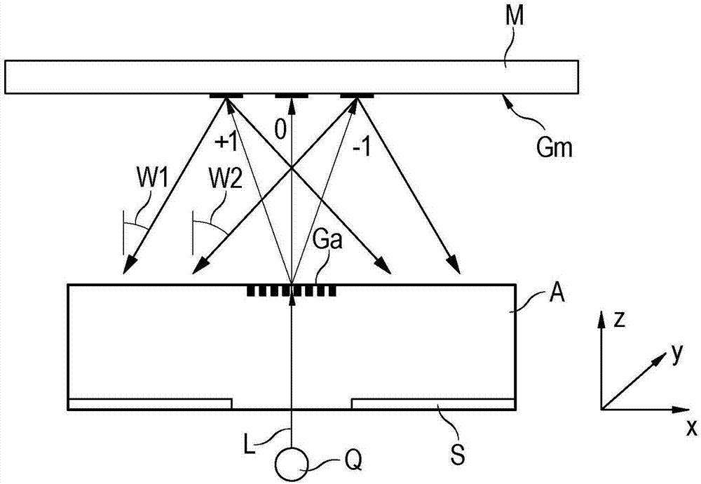
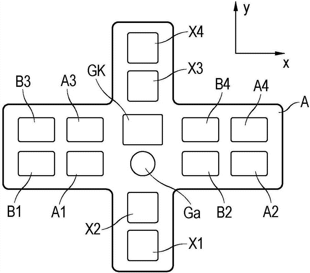
[0017] figure 1 The basic structure of the position-measuring device according to the invention is schematically shown with a planar scanning plate A extending in both directions X and Y and a planar measuring standard M parallel to the scanning plate A. figure 2 A plan view of the side of the scanning plate A facing the measuring standard M is shown.

[0018] The light L of the light source Q passes through the transparent scanning reticle A in the Z direction and impinges on the partition grid Ga, which is arranged on the side of the scanning reticle A facing the measuring standard M. The separation grid Ga separates the light into a plurality of sub-rays +1, 0, -1 of different diffraction orders. The three sub-rays +1, 0, −1 impinge on the optical grid Gm, which is arranged on the side of the measuring standard M facing the scanning plate A. The optical grid Gm is a cross grid, which re-segregates the sub-rays +1, 0, -1 into different diffraction orders, that is, prefera...


PUM


Abstract

An optical position-measuring device three linearly independent spatial directions includes a scale and a scanning reticle. The device is provided with a splitter grating disposed on the scanning reticle and adapted to split light into sub-beams of different diffraction orders; and an optical grating disposed on the scale and adapted to further split the sub-beams and to recombine them after they have been reflected back from the scanning reticle. In addition, the device is provided with a plurality of grating fields disposed on a side of the scanning reticle that faces the scale, with the grating fields acting as diffractive optics that influence the further split sub-beams on the scale; and a separating grating disposed on the scanning reticle and used for separating light, as interfering sub-beams, reflected between the scale and the scanning reticle in a plurality of times. The position-measuring device is characterized in that the plurality of the grating fields configured as phase gratings have different step heights.

Description

technical field [0001] The invention discloses an optical position-measuring device with a measuring standard and a scanning plate, whose position relative to one another can be determined in three linearly independent spatial directions by means of a plurality of interfering light rays. Background technique [0002] A position measuring device of this type is known from DE 10 2014 218 623 A1 by the applicant. A particular advantage of such a position-measuring device is that the relative position of two objects can be measured in three spatial directions by means of a single position-measuring device. Two of these spatial directions are linearly independent of each other (i.e. achieved by their being arranged perpendicular to each other) and are parallel to the planar gage and also parallel to the planar scanning plate, the third spatial direction is perpendicular to the two previous and corresponds to the spacing or spacing changes between the scanning plate and the gage....

Claims


Application Information

Patent Timeline
Patent Type & Authority Applications(China)
IPC IPC(8): G01B11/00G01D5/347G01D5/38
CPCG01B11/00G01D5/347G01D5/38G01B9/02017G01B9/02034G01B2290/30G01B2290/65
Inventor 彼得·施佩克巴赫尔托比亚斯·格林德尔克里斯蒂安·博梅尔约瑟夫·魏德曼
Owner DR JOHANNES HEIDENHAIN GMBH
Learn More