
Fault actual measurement data-based transmission line length calibration method

A technology of measured data and calibration method, which is applied in the direction of measuring devices, instruments, etc., can solve the problems of increased errors in fault ranging results, etc., and achieve the effect of small errors in ranging results and increasing ranging errors

Pending Publication Date: 2017-07-28
KUNMING UNIV OF SCI & TECH
View PDF7 Cites 2 Cited by
  • Summary
  • Abstract
  • Description
  • Claims
  • Application Information

AI Technical Summary

Problems solved by technology

[0003] The present invention provides a transmission line length verification method based on fault actual measurement data, which is used to solve the problem that the current transmission line length is fixed, which increases the error of fault distance measurement results

Method used


Image

  • Fault actual measurement data-based transmission line length calibration method
  • Fault actual measurement data-based transmission line length calibration method
  • Fault actual measurement data-based transmission line length calibration method

Examples


Embodiment 1

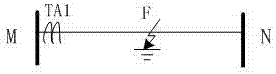
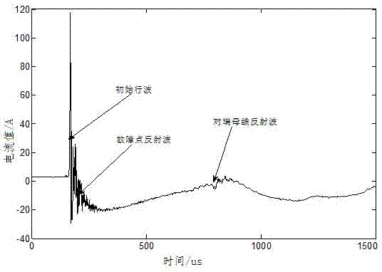
[0014] Example 1: At 13:30:10 on October 3, 2013, phase C of circuit II of a line fails, the reference length of line MN is 93.1km (the length when the line is erected), traveling wave distance measurement installed on the M side of the line The sampling rate of the device is 1MHz, and the traveling wave of phase C fault current of line MN is like image 3 Shown.

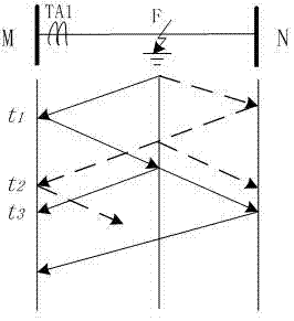
[0015] Collect line MM measuring terminal TA by traveling wave fault location device 1 The fault current traveling wave is recorded separately, and the initial traveling wave head of the fault, the reflected wave head of the opposite bus bar and the reflected wave head of the fault point arrive at the measuring end TA 1 The moments are recorded as t 1 , t 2 , t 3 , which is t 1 =0.887260s, t 2 =0.887280s, t 3 =0.887873s.

[0016] The sum of the time difference between the reflected wave head of the opposite bus bar and the reflected wave head of the fault point and the initial traveling wave head of the fault: ∆t= ( t 2 -...

Embodiment 2

[0018] Example 2: At 17:06:29 on May 12, 2012, phase C of a line fails, the reference length of line MN is 41.3km (the length when the line is erected), and the traveling wave distance measuring device installed on the M side of the line is sampled The rate is 1MHz, and the C-phase fault current traveling wave of line MN is like Figure 4 Shown.

[0019] Collect line MM measuring terminal TA by traveling wave fault location device 1 The fault current traveling wave is recorded separately, and the initial traveling wave head of the fault, the reflected wave head of the opposite bus bar and the reflected wave head of the fault point arrive at the measuring end TA 1 The moments are recorded as t 1 , t 2 , t 3 , which is t 1 =0.411582s, t 2 =0.411684s, t 3 =0.411780s.

[0020] The calculation of the sum of the time difference between the reflected wave head of the opposite bus bar and the reflected wave head of the fault point and the initial traveling wave head: ∆t= ( t 2 -t 1 )+( t 3 ...


PUM


Abstract

The present invention relates to a fault actual measurement data-based transmission line length calibration method, and belongs to the electric power system relay protection technology field. The method of the present invention comprises the steps of when a transmission line MN goes wrong, propagating a fault current traveling wave to the measurement end of a bus M; acquiring a fault current traveling wave at the measurement end of a line MM by a traveling wave fault distance measurement device, and separately recording the time when a fault initial traveling wave head wave tip, an opposite-end bus reflection wave tip and a fault point reflection wave tip reach the measurement end, and then calculating the sum of the time difference of the opposite-end bus reflection wave tip and the fault initial traveling wave head wave tip and the time difference of the fault point reflection wave tip and the fault initial traveling wave head wave tip separately, and finally utilizing the empirical wave velocity to calibrate the total length of the line MN. According to the present invention, the transmission line length is calibrated based on the fault actual measurement data, so that the calculated and used line length gets closer to the actual line length, and a distance measurement result error becomes small.

Description

Technical field [0001] The invention relates to a method for verifying the length of a transmission line based on actual fault measurement data, and belongs to the technical field of power system relay protection. Background technique [0002] At present, the length of the transmission line is based on the nominal distance when the line is erected. However, the length of the transmission line will become longer with the running time. The length of the transmission line is required in the traveling wave fault location. If the nominal length is used It will increase the error of the ranging result, and the line length needs to be recalculated. Summary of the invention [0003] The invention provides a method for verifying the length of a transmission line based on actual fault measurement data to solve the problem that the length of the current transmission line is fixed and the error of the fault location result increases. [0004] The technical scheme of the present invention is: a...

Claims


Application Information

Patent Timeline
Patent Type & Authority Applications(China)
IPC IPC(8): G01B21/02
CPCG01B21/02
Inventor 浦通李家汉刘远飞
Owner KUNMING UNIV OF SCI & TECH
Learn More