Die mechanism capable of realizing core-pulling by adopting sliding blocks combined with angle lifters

A sliding block and sloping roof technology, which is applied in the fields of plastic injection molding and metal die-casting molds, can solve the problems of high labor intensity, low production efficiency, and inability to guarantee safety.

Inactive Publication Date: 2017-08-01
牟维军
View PDF0 Cites 2 Cited by
  • Summary
  • Abstract
  • Description
  • Claims
  • Application Information

AI Technical Summary

Problems solved by technology

Although this structure is simple and can produce perfect products, the production efficiency is low and the labor intensit

Method used


Image

  • Die mechanism capable of realizing core-pulling by adopting sliding blocks combined with angle lifters
  • Die mechanism capable of realizing core-pulling by adopting sliding blocks combined with angle lifters
  • Die mechanism capable of realizing core-pulling by adopting sliding blocks combined with angle lifters

Examples


Embodiment Construction

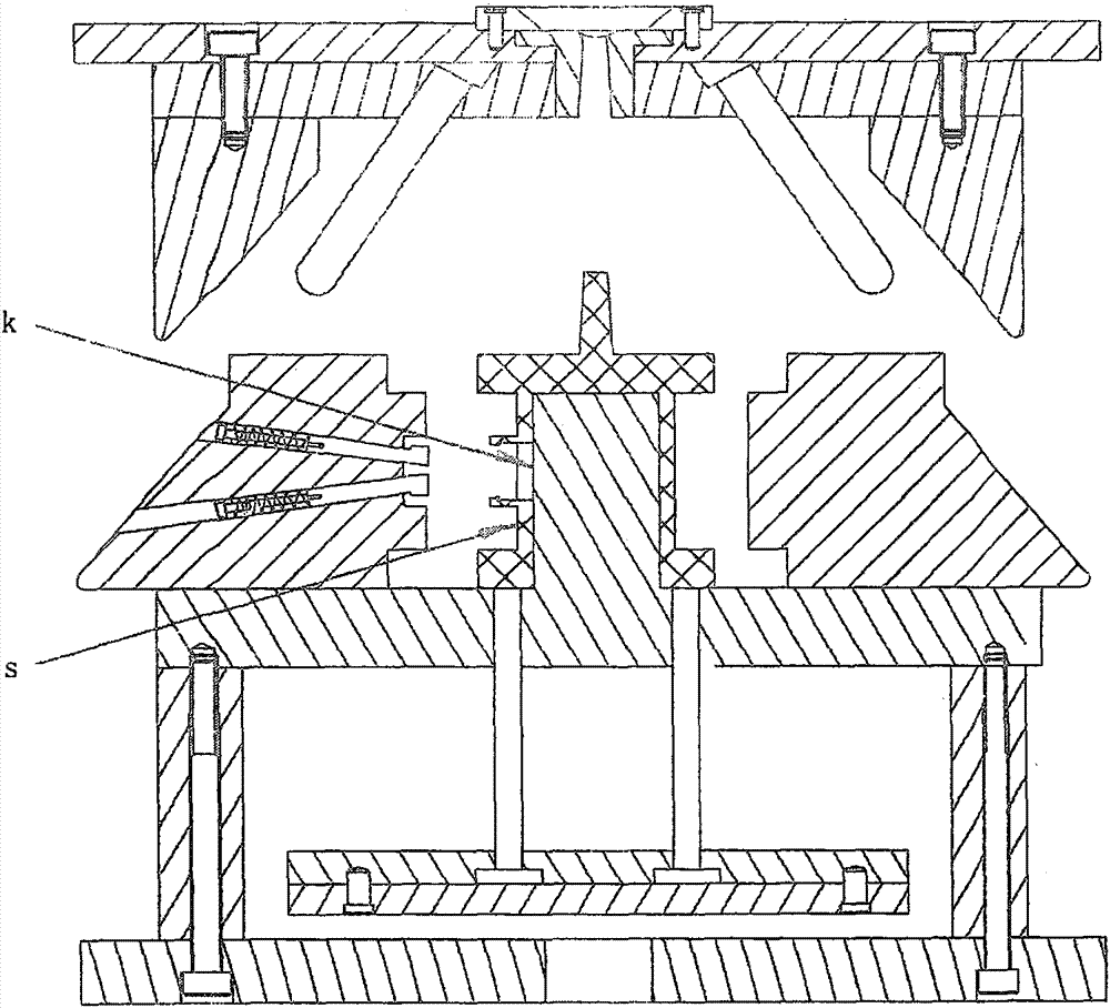
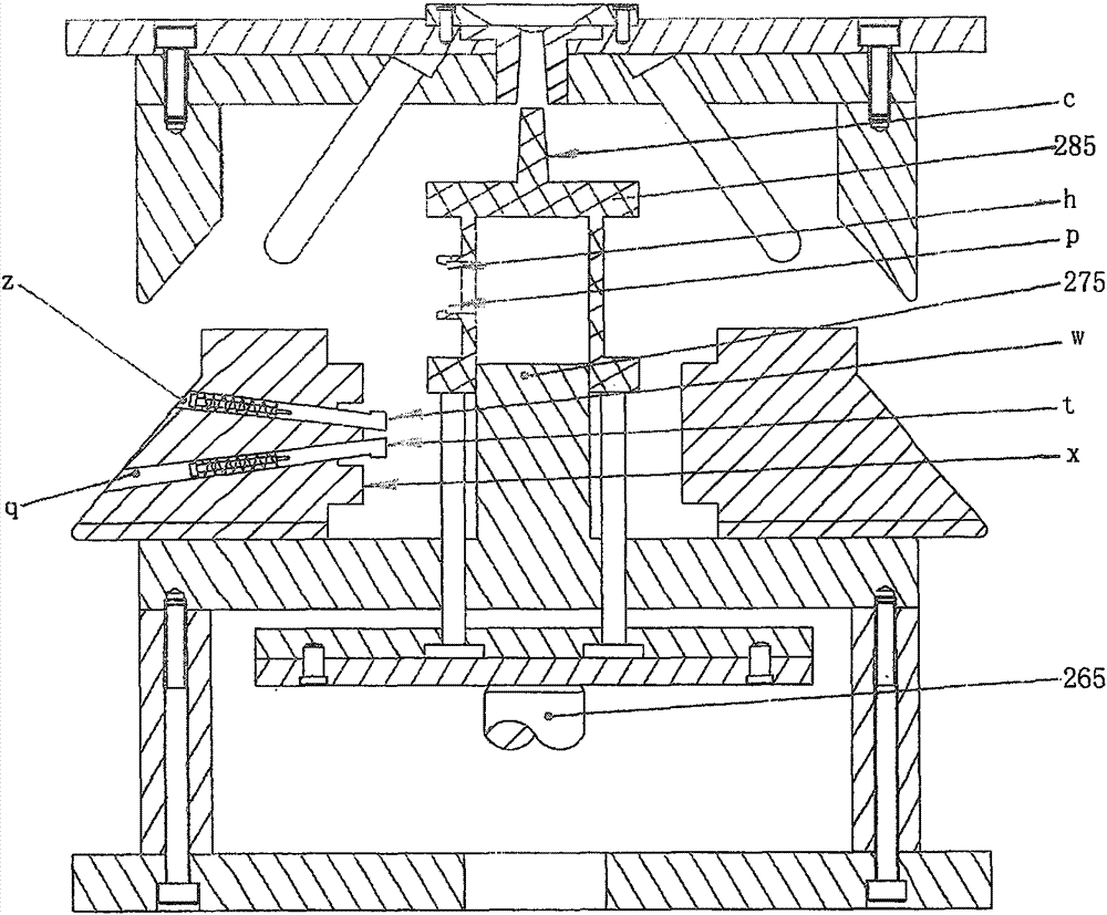
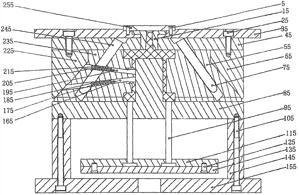
[0037] 1. As shown in the figure, it is the mold mechanism of the slider and the inclined top combined with core pulling. It includes a fixed mold and a movable mold. The fixed mold consists of: positioning ring (255), first screw (5), gate Set (15), second screw (25), fixed mold seat plate (35), fixed mold backing plate (45), second oblique pressure block (65), second oblique guide post (75), first oblique pressure Block (225), the first inclined guide post (245), the fixed mold seat plate (35) and the locating ring (255) are fastened and connected with the first screw (5), and the fixed mold seat plate (35) step A sprue sleeve (15) is installed in the hole, and the sprue sleeve (15) passes through the fixed mold backing plate (45), and the sprue sleeve (15) is closely attached to the product (285), and the fixed mold backing plate ( 45) are installed in the inclined step hole of the first inclined guide post (245) and the second inclined guide post (75), and the first inclin...


PUM


Abstract

The invention relates to a die mechanism capable of realizing core-pulling by adopting sliding blocks combined with angle lifters. The die mechanism comprises a fixed die and a moving die, wherein a fixed clamping plate (35), a fixed mold support plate (45), a first inclined pressure block (225) and a second inclined pressure block (65) are tightly connected by second screws (25); a moving mold plate (85), spacer blocks (145) and a moving clamping plate (155) are tightly connected by third screws (105); a first sliding block (235) and a second sliding block (55) are arranged above the moving mold plate (85); the first angle lifter (195), a first spring (205) and a first pull rod (225) are mounted in a first pull rod hole e of the first sliding block (235); the second angle lifter (165), a second spring (175) and a second pull rod (185) are mounted in a second pull rod hole q; the end surface W of the first angle lifter (195) and the end surface t of the second angle lifter (165) are in contact with the side surface K of a forming mold core (275) when the die is closed.

Description

technical field [0001] The invention relates to a plastic injection mold and a metal die-casting mold, which is a core-pulling mold mechanism combined with a slide block and an inclined top. Background technique [0002] After metal die-casting parts and plastic injection parts are molded, if there are upward and downward protrusions on the side of the product, and at the same time, there are upward or downward undercuts on the upper and lower protrusions, the existing technology is to reduce the depth of the upper and lower undercuts , and then the undercut is removed by forced demoulding. This structure is prone to breaking the upper and lower undercuts when the undercut is removed, resulting in the scrapping of the product. Effect. Another way is to design the parts at the upper and lower undercuts of the product and the molded product into a movable structure. When the mold is opened, the product and the movable parts are pushed out of the mold together, and then the pr...

Claims


Application Information

Patent Timeline
IPC IPC(8): B29C45/33B29C45/40B22D17/22
CPCB29C45/33B22D17/2236B29C45/4005B29C2045/338
Inventor 牟维军
Owner 牟维军
Why Eureka
Try Eureka